
Tentering and setting machine baking oven

A stenter setting machine and oven technology, applied in the direction of heating/cooling fabrics, textiles and papermaking, fabric surface trimming, etc., can solve the problem of low utilization rate of hot air, achieve the effect of improving utilization rate and saving heat energy

Active Publication Date: 2013-05-08
无锡市信文机械制造有限公司
View PDF4 Cites 13 Cited by
  • Summary
  • Abstract
  • Description
  • Claims
  • Application Information

AI Technical Summary

Problems solved by technology

To solve the problem of low utilization rate of hot air in the oven of the stenter setting machine in the prior art

Method used


Image

  • Tentering and setting machine baking oven

Examples


Embodiment Construction

[0010] The technical solutions of the present invention will be further described below in conjunction with the accompanying drawings and through specific implementation methods.

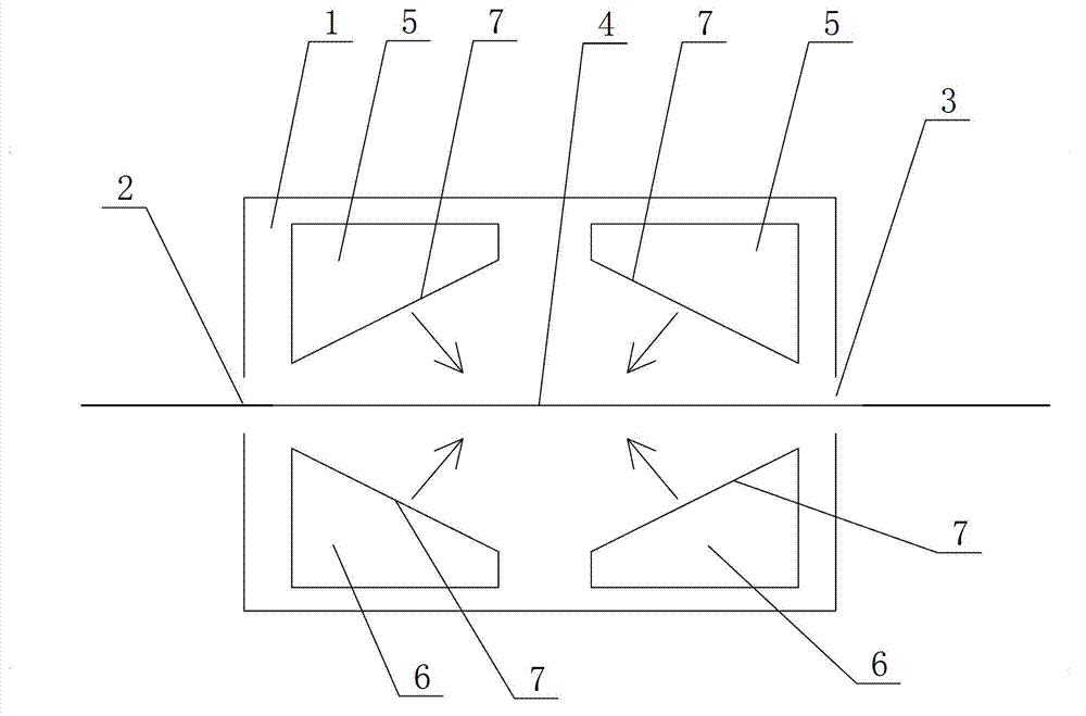
[0011] see figure 1 as shown, figure 1 It is a structural schematic diagram of the oven for the stenter setting machine provided in Embodiment 1 of the present invention.

[0012] In this embodiment, an oven for a stenter setting machine comprises an oven box 1, two ends of the oven box 1 are provided with a cloth inlet 2 and a cloth outlet 3, and a conveyor belt 4 passes through the cloth inlet of the oven box 1. The mouth 2 and the cloth outlet 3 are set, and there are multiple groups of hot air passages correspondingly arranged above and below the conveyor belt 4 in the oven body 1 (only two groups of hot air passages located at the outermost end are shown in the figure, in the In actual application, there are multiple sets of hot air ducts arranged in the oven), and the two sets of hot air duc...


PUM


Abstract

The invention discloses a tentering and setting machine baking oven which comprises a baking oven body, wherein two ends of the baking oven body are provided with a cloth inlet and a cloth outlet; a conveying belt is arranged by passing through the cloth inlet and the cloth outlet of the baking oven body, and a plurality of groups of hot air channels are correspondingly arranged above and below the conveying belt in the baking oven body; air blowing ports are formed in the hot air channels; and air is supplied to the inner side of the baking oven body by air blowing ports of the two groups of hot air channels positioned at the outermost end of the plurality of groups of hot air channels. The air is supplied to the inner side of the baking oven body by air blowing ports of the hot air channels at two ends of the tentering and setting machine baking oven, so that hot air forms air curtains at the cloth inlet and the cloth outlet, and hot air in the baking oven is difficult to be exhausted from the cloth inlet and the cloth outlet, therefore the heat in the baking oven hardly diffuses outside, further, the hot air utilization ratio is improved, and the heat energy can be saved by 5%.

Description

technical field [0001] The invention relates to a stenter setting machine, in particular to an oven for the stenter setting machine. Background technique [0002] After the original gray cloth is processed and formed, it must be stretched to become the fabric to be produced. In order to prevent the gray cloth from being torn due to local stress during stretching, it needs to be dipped. Drying and setting treatment is required. The existing stenter setting machine oven includes an oven box. The two ends of the oven box are provided with a cloth inlet and a cloth outlet. The conveyor belt is arranged in the oven box, and the oven box There are multiple sets of hot air ducts correspondingly arranged above and below the conveyor belt, and the hot air passes through the hot air ducts to dry and shape the gray cloth on the conveyor belt. The air supply mode of the air outlet is straight up and down, so that the hot air near the two ends of the cloth inlet and outlet will spread o...

Claims


Application Information

Patent Timeline
IPC IPC(8): D06C7/02D06C3/00
Inventor 华文辉
Owner 无锡市信文机械制造有限公司
Learn More