Headboxes for fiber web machines

A technology of fiber web machine and headbox, which is applied in the direction of paper machine, paper machine wet end, textile and paper making, etc. It can solve the problems affecting the investment cost of the machine and achieve the effect of eliminating demand

Active Publication Date: 2016-06-22
VALMET TECH OY
View PDF7 Cites 0 Cited by
  • Summary
  • Abstract
  • Description
  • Claims
  • Application Information

AI Technical Summary

Problems solved by technology

The manufacture of headboxes is capital intensive due to the large quantities of each component and the high manufacturing precision required
In addition, each component increases the length of the headbox in the machine direction, which affects the investment cost of the entire machine

Method used


Image

  • Headboxes for fiber web machines
  • Headboxes for fiber web machines
  • Headboxes for fiber web machines

Examples


Embodiment Construction

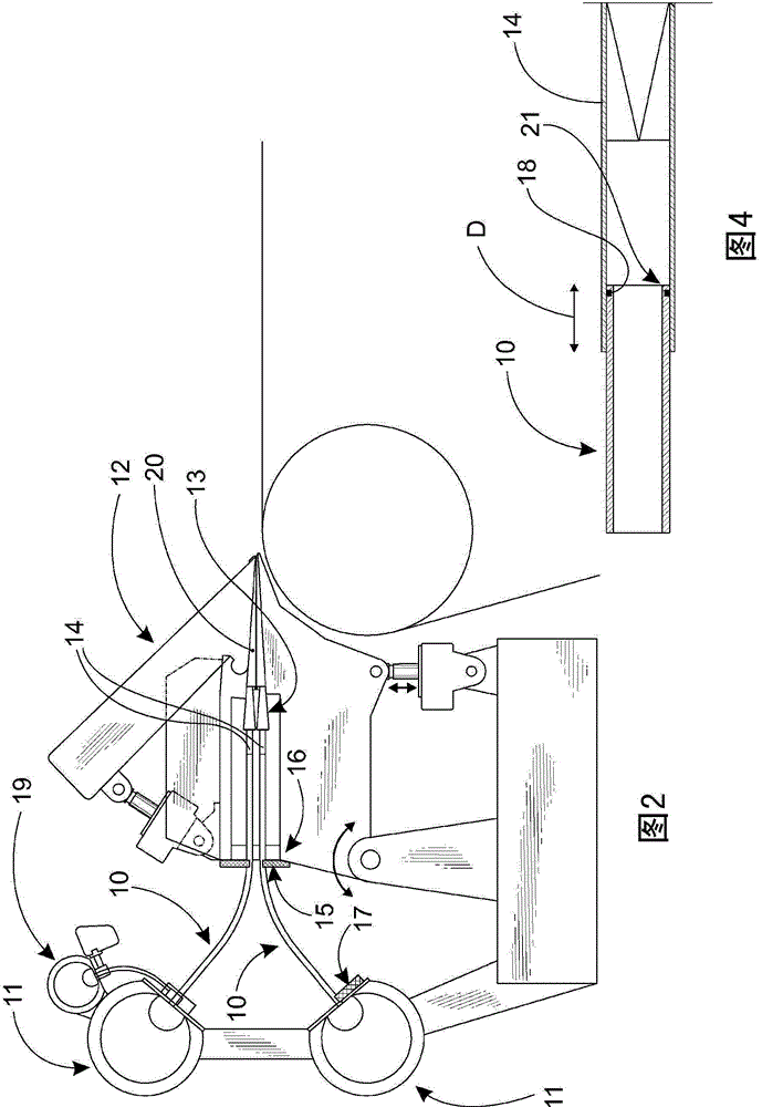
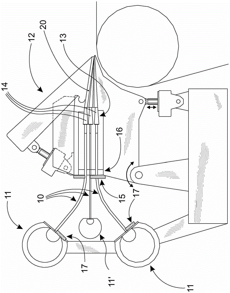
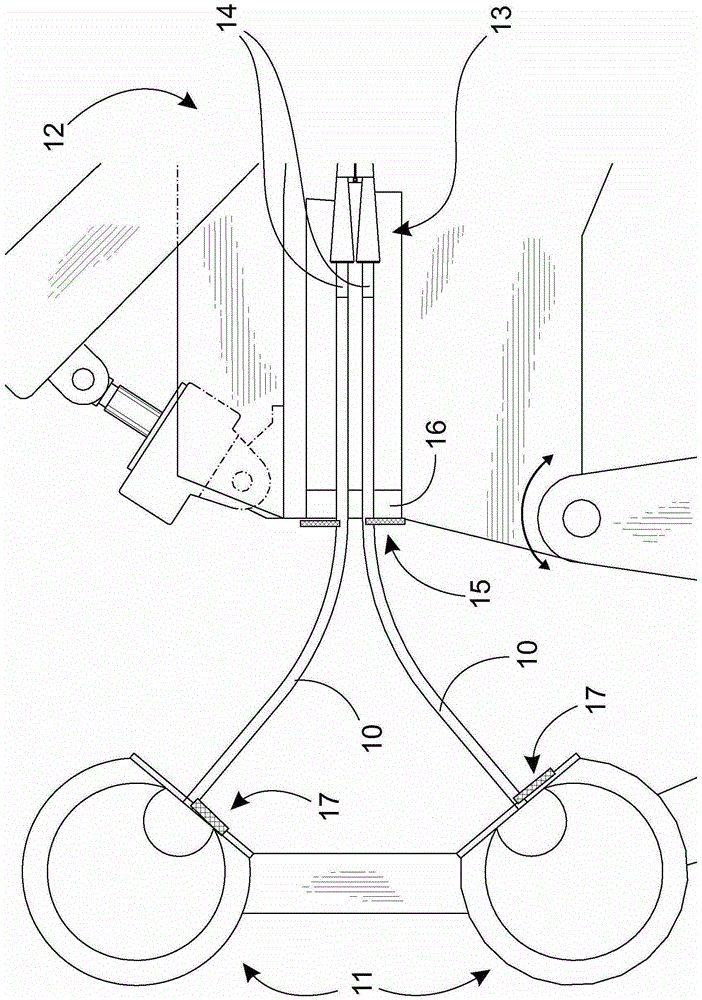
[0014] Figure 1 to Figure 3 is a side sectional view of an embodiment of a headbox 12 for a fiber web machine. The headbox 12 comprises, in a manner known per se, a turbulence generator 13 equipped with flow tubes 14 . For example, at least one manifold 11, 11' The manifold 11, 11' is usually a tubular manifold 11 for example for pulp suspension, but it could also be a manifold 11' for example for dilution water, or another type of pulp suspension delivery system such as a so-called Octopus manifold (octopusmanifold, not shown).

[0015] exist figure 1 , two pulp suspension manifolds 11 and one dilution water manifold 11' are connected to the headbox 12 through these intermediate pipes 10 to provide a water layer. exist figure 2 , an intermediate pipe 10 is used to connect the two manifolds 11 to the headbox 12. A manifold 19 of dilution water for the basis weight profile of the fiber web is located close to the second manifold 11 from which the dilution water is ...


PUM


Abstract

The invention relates to a headbox for a fiber web machine including a turbulence generator (13) equipped with flow pipes (14) to which at least one manifold (11, 11') is arranged to be connected using intermediate pipes (10). At least part of the intermediate pipes are arranged to extend within the flow pipe of the turbulence generator.

Description

technical field [0001] The invention relates to a headbox for a fiber web machine. The headbox includes a turbulence generator having a flow tube to which a manifold is arranged to be connected with an intermediate tube. Background technique [0002] The headbox of the fiber web machine is supplied with web forming pulp from a manifold or similar delivery pipe. For example, a multi-layer headbox can have multiple (eg 3 to 5) manifolds. The manifold can be connected to the headbox by eg a number of flexible, elastic intermediate pipes. The web forming pulp is supplied to the headbox through these intermediate pipes in the desired manner (across its main width). [0003] A prior art solution is presented in International Patent Application Publication WO01 / 38775A1. However, a significant drawback of this solution is that the connection of the structural parts of the headbox using rubber hoses is carried out via separate fitting elements or similar. Using these elements on...

Claims


Application Information

Patent Timeline
Patent Type & Authority Patents(China)
IPC IPC(8): D21F1/06
CPCD21F1/02D21F1/024D21F1/026D21F1/06
Inventor 扬内·拉皮萨米·安蒂莱宁
Owner VALMET TECH OY
Why Eureka
Try Eureka