Slide arrangement for cable drawer

A drawer and slideway technology, applied in drawers, optics, light guides, etc., can solve problems such as fiber bending, signal strength attenuation, and signal loss

Active Publication Date: 2006-08-02
COMMSCOPE TECH LLC
View PDF4 Cites 11 Cited by
  • Summary
  • Abstract
  • Description
  • Claims
  • Application Information

AI Technical Summary

Problems solved by technology

Excessive movement can bend the fiber, resulting in attenuation or loss of signal strength
When an

Method used


Image

  • Slide arrangement for cable drawer
  • Slide arrangement for cable drawer
  • Slide arrangement for cable drawer

Examples


Embodiment Construction

[0046] Various features of the present invention illustrated in the accompanying drawings will now be described in detail. Wherever possible, the same reference numbers will be used throughout the drawings to refer to the same or like parts.

[0047] I. Drawer device

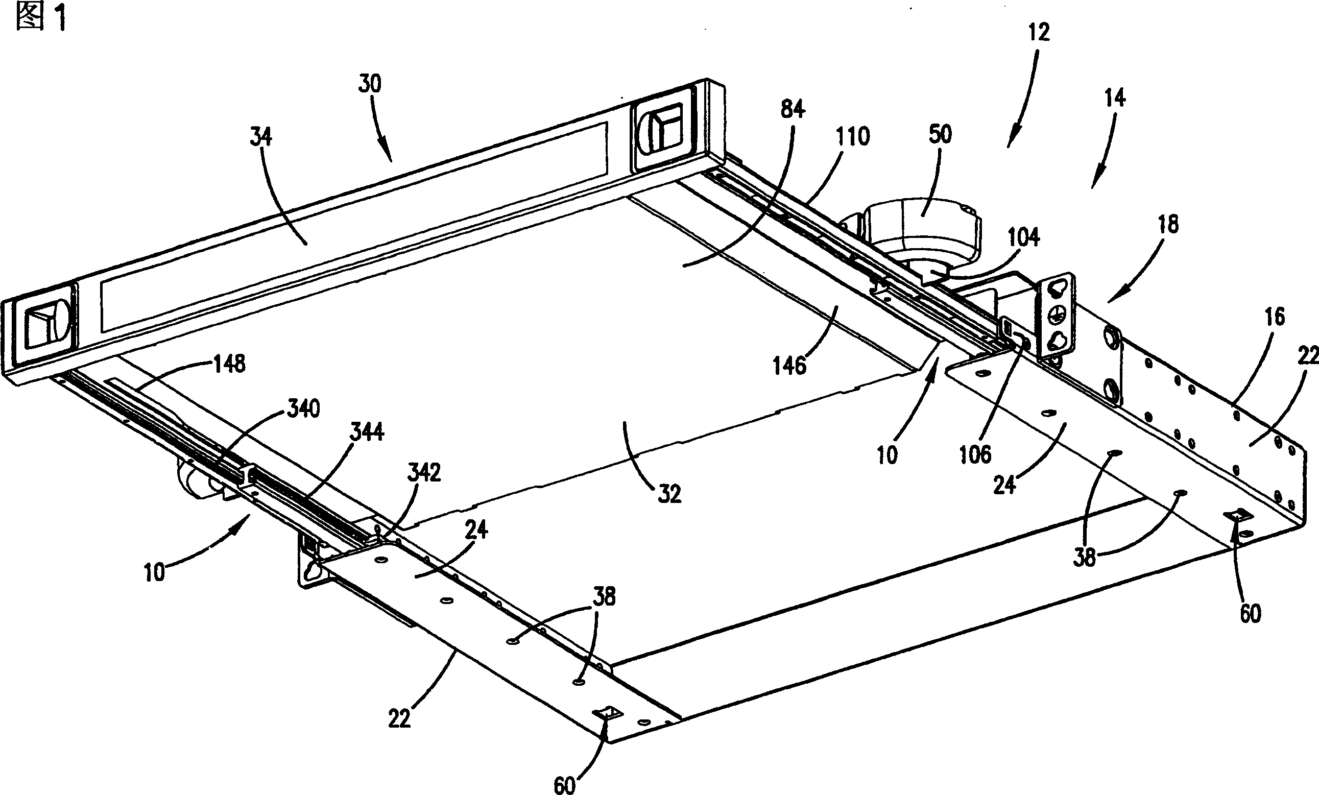
[0048] Referring to Figure 1, there is shown a drawer slide 10 for a cable management board or module 12 in accordance with the present invention. Module 12 includes a drawer arrangement 14 . Typically, the drawer assembly 14 is configured to be mounted to a rack, cabinet, enclosure, or other mounting fixture (not shown). In some applications, multiple drawer assemblies 14 incorporating features of the present invention may be mounted to a single rack or enclosure to provide a system of cable management modules 12 .

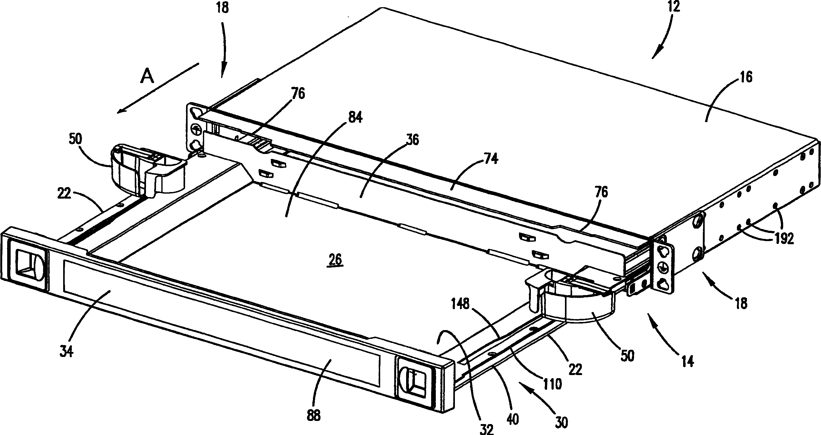
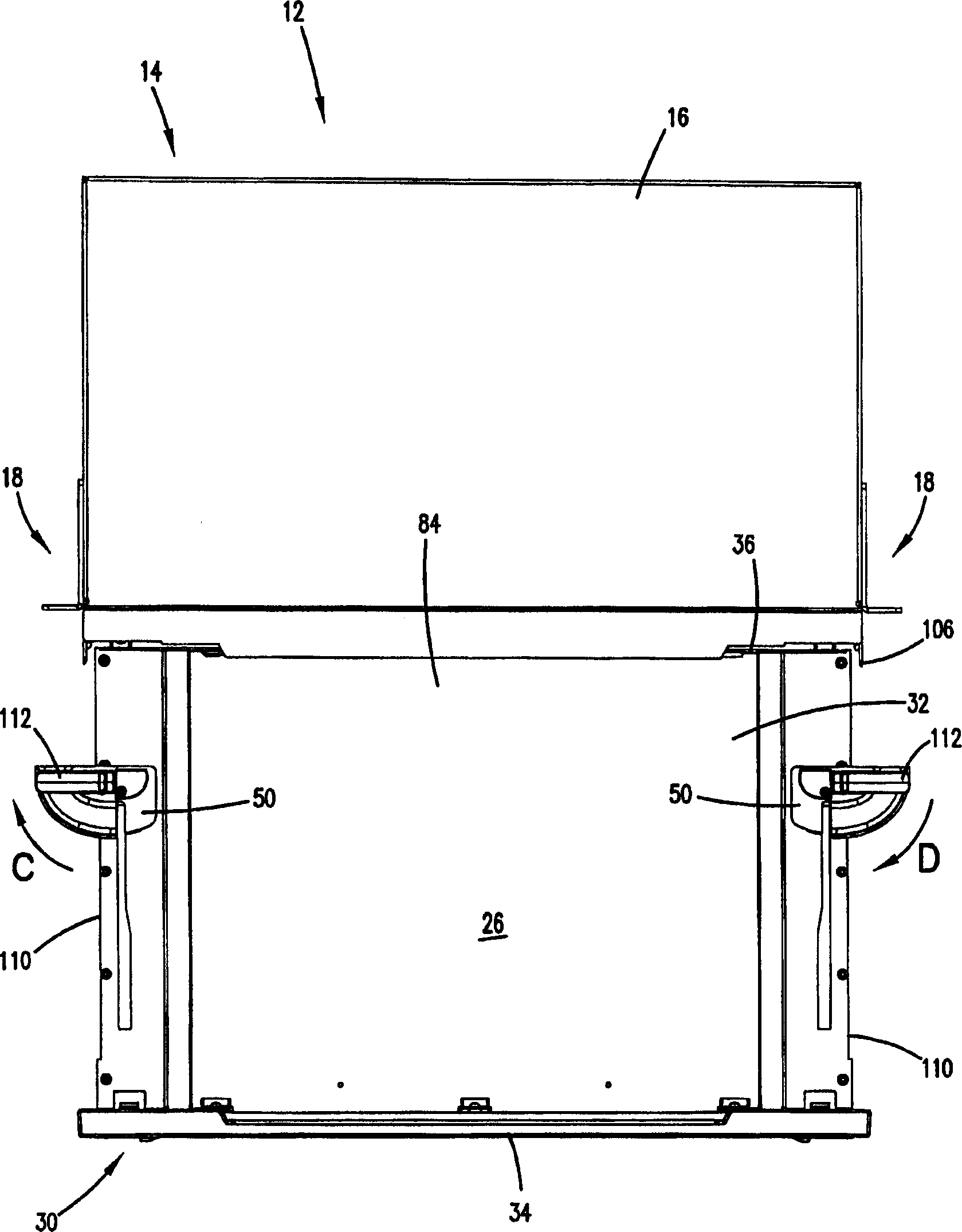
[0049] As shown in FIGS. 1-4 , the drawer unit 14 includes a frame or chassis 16 and a drawer 30 . Drawer slide 10 operably interconnects drawer 30 and chassis 16 ; that is, drawer 30 is design...


PUM


Abstract

A drawer slide having first and second rails interconnected by a center rail. The center rail includes a spool configured to provide half-speed travel of the center rail relative to the travel of the first rail. The drawer slide is configured for use with a drawer assembly having a drawer and a chassis. The drawer assembly further includes a radius limiter secured to the center rail. The radius limiter travels at half-speed relative to the drawer. The radius limiter also automatically rotates relative to the travel of the drawer. The chassis includes sides including threaded backing plates, and mounting brackets. The mounting brackets include tri-lobed holes for receipt of a reciprocally shaped washer and a fastener for mounting the brackets to the chassis sides.

Description

technical field [0001] The present invention relates to the management of fiber optic cables. More specifically, the present invention relates to storage of fiber optic cables and equipment for use in the telecommunications industry. Background technique [0002] Cable storage devices and devices have been used to prevent unnecessary or excessive movement of optical fibers. Examples of some known devices or devices are disclosed in US Patent Nos. 5,066,149 and 6,504,988, both assigned to ADC Telecommunications Corporation, which are incorporated by reference. Other cable storage devices and devices are disclosed in U.S. Patent Application Serial No. 09 / 900,465, filed July 6, 2001, and U.S. Patent Application No. 10 / 346,914, filed January 15, 2003, both of which Both applications have been assigned to ADC Telecom, Inc., and both patents are incorporated by reference. [0003] Typically, these devices and devices are arranged such that unnecessary or excessive movement of t...

Claims


Application Information

Patent Timeline
IPC IPC(8): G02B6/44A47B88/49
CPCG02B6/4452A47B88/08A47B2210/0059G02B6/4439G02B6/4453A47B2210/001G02B6/4455A47B88/49Y10T29/49895Y10T29/49641A47B88/906A47B88/50G02B6/4478A47B88/443A47B88/40A47B88/44A47B88/969A47B2210/007G02B6/4457
Inventor 凯瑟琳·M·巴恩斯贾斯廷·R·霍顿托马斯·C·蒂纳奇托马斯·L·巴恩斯
Owner COMMSCOPE TECH LLC
Why Eureka
Try Eureka