

Floor plate truss pouring structure
A floor slab and truss technology, which is applied to floor slabs, building components, building structures, etc., can solve the problems of low labor efficiency, insufficient use of concrete beam support, and difficult construction, so as to improve labor efficiency and reduce construction difficulty. , Improve the effect of coverage area
Inactive Publication Date: 2013-05-08
南方锐博新型建材有限公司
View PDF5 Cites 2 Cited by
- Summary
- Abstract
- Description
- Claims
- Application Information
AI Technical Summary
Problems solved by technology
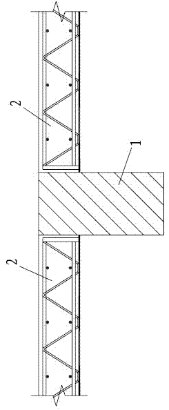
[0002] The floor slab truss pouring structure in the prior art is as figure 1 As shown, the floor slabs 2 are generally distributed on both sides of the concrete beam 1, so that it is necessary to pour on both sides of the concrete beam during construction, so that on the one hand, the supporting function of the concrete beam is not fully utilized, and on the other hand, it also causes The construction is difficult and the labor efficiency is low
Method used
View moreImage
Smart ImageViewing Examples

Examples
Embodiment
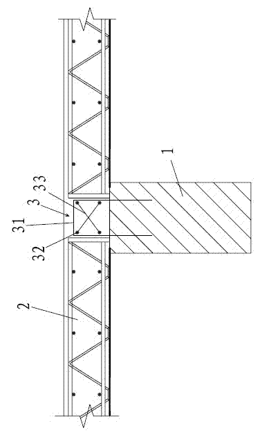
[0015] Embodiment: a floor slab truss pouring structure, such as figure 2 As shown, it includes a concrete beam 1 and a floor deck 2, the floor deck 2 is arranged above the concrete beam 1, and the floor deck 2 has a connecting portion 3 connected to the concrete beam 1; the connecting portion 3 includes four pieces divided into two rows The connecting ribs 32 arranged in parallel are fixedly connected with fixed ribs 33 between the diagonally distributed connecting ribs 32 , and the connecting ribs 32 are fixedly connected with a U-shaped stirrup 31 inserted into the concrete beam 1 .
Login to View More PUM
 Abstract
The invention relates to the building field, in particular to a floor plate truss pouring structure. The floor plate truss pouring structure comprises a concrete beam and a floor support plate, and the floor support plate is arranged above the concrete beam and provided with a connecting part connected with the concrete beam. The floor plate truss pouring structure can effectively improve labor efficiency, reduce construction difficulty, and meanwhile can benefit to fully using of bearing effect of the concrete beam.
Description
technical field [0001] The invention relates to the field of construction, in particular to a floor plate truss pouring structure. Background technique [0002] The floor slab truss pouring structure in the prior art is as figure 1 As shown, the floor slabs 2 are generally distributed on both sides of the concrete beam 1, so that it is necessary to pour on both sides of the concrete beam during construction, so that on the one hand, the supporting function of the concrete beam is not fully utilized, and on the other hand, it also causes The construction is difficult and the labor efficiency is low. Contents of the invention [0003] The purpose of the present invention is to provide a floor slab truss pouring structure, which can effectively improve labor efficiency, reduce construction difficulty, and is also conducive to fully utilizing the supporting function of concrete beams. [0004] The above technical purpose of the present invention is achieved by the following ...
Claims
Login to View More Application Information
Patent Timeline
 IPC IPC(8): E04B5/32
Inventor陈永德刘继国陈丽琴
Owner南方锐博新型建材有限公司