Seal valve switch electric machine

A technology for switching motors and sealing valves, applied in shaft seals, valve details, valve devices, etc., can solve the problems of inaccurate control of valve medium flow, no self-locking ability of electric devices, large flow fluctuations, etc., and achieve simple structure , Reduce drive power, save energy

Inactive Publication Date: 2013-05-08
张家政
View PDF7 Cites 3 Cited by
  • Summary
  • Abstract
  • Description
  • Claims
  • Application Information

AI Technical Summary

Problems solved by technology

[0003] (1) Large valves must be equipped with a large and complex transmission mechanism, resulting in increased costs;
[0004] (2) The flow of the valve medium cannot be accurately controlled. When the valve needs to be rotated at a small angle, the above valve cannot be realized;
[0005] (3) When the valve is closed, the electric device has no self-locking ability, resulting in large flow fluctuations;

Method used


Image

  • Seal valve switch electric machine
  • Seal valve switch electric machine
  • Seal valve switch electric machine

Examples


Embodiment 1

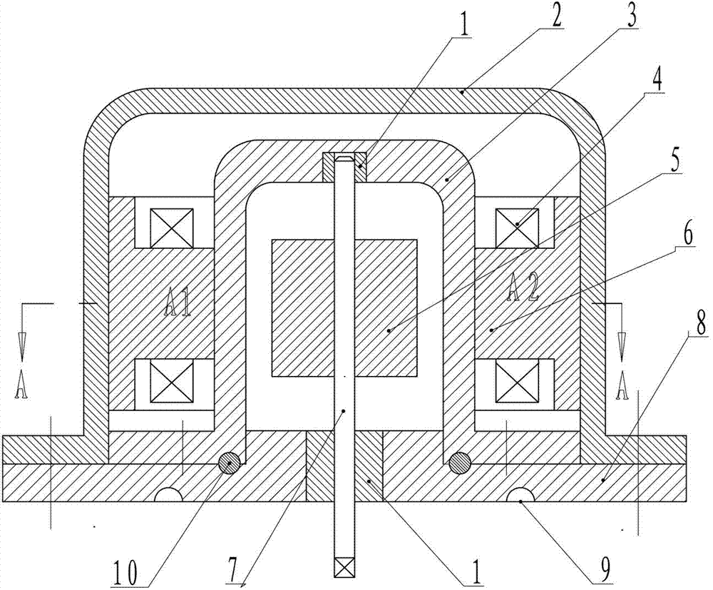
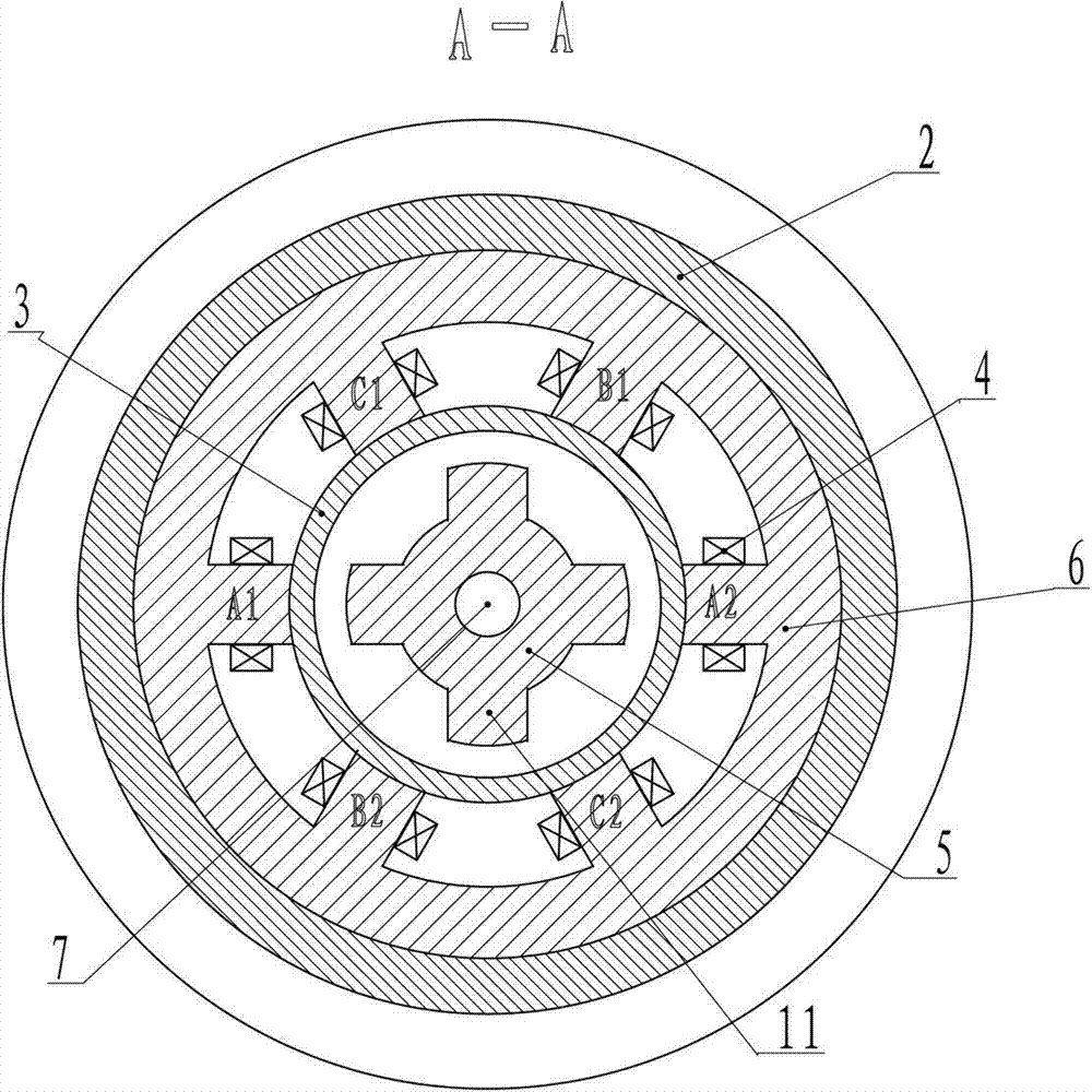
[0029] Example 1 (see figure 1 , 2 ):

[0030] Depend on figure 1 , 2 The illustrated embodiment 1 includes a housing 2, a stator, a rotor, a rotor shaft 7, a spacer 3 and a base 8; the spacer 3 is located between the rotor and the stator, and the spacer 3 is fixed on the base 8 with screws. A first sealing ring 10 is provided between the spacer 3 and the base 8; the upper end of the rotor shaft 7 is installed on the top wall of the spacer 3, and the lower end of the rotor shaft 7 extends out of the base 8; the stator includes a stator iron Core 6 and stator coil 4, each stator coil 4 is sleeved on its corresponding stator pole; An annular groove 9 for placing a sealing rubber ring is provided on the bottom surface of the base 8; The housing 2 is fixed on the base by bolts 8 on.

[0031] The rotor is a first soft magnetic rotor 5 , and soft magnetic rotor poles 11 corresponding to the stator poles are evenly distributed on the side wall of the first soft magnetic rotor...

Embodiment 2

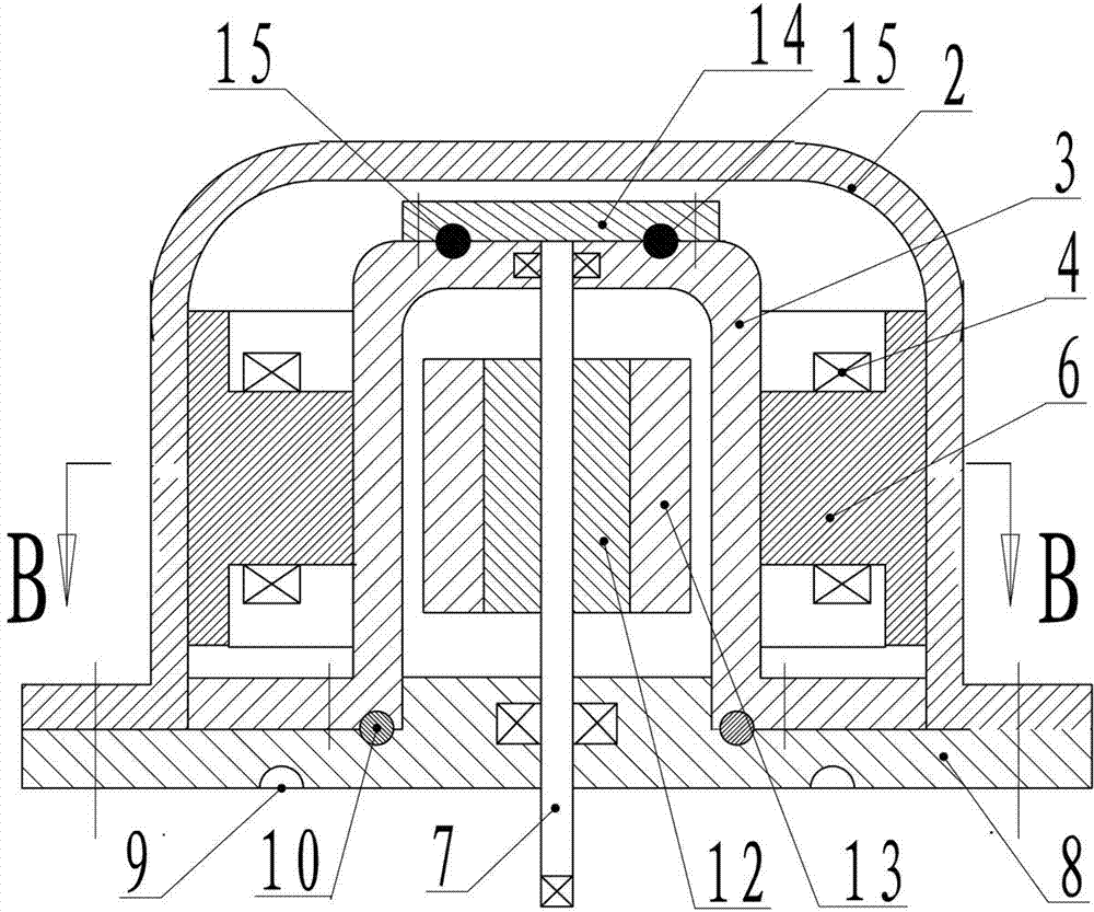
[0037] Example 2 (see Figure 3-4 ):

[0038] Depend on image 3 , 4 Embodiment 2 can be known, and embodiment 1 is different in that: described rotor is made of second soft magnetic body rotor magnetic pole 12 and the permanent magnet rotor magnetic pole 13 that is evenly distributed on the second soft magnetic body rotor magnetic pole 12 sidewall, and described permanent magnet rotor The number of magnetic poles 13 is adapted to the number of stator magnetic poles.

[0039] The number of the stator poles is 6, and the number of the permanent magnet rotor poles 13 is 4.

[0040] The two ends of the rotor shaft 7 are respectively mounted on the top wall and the base 8 of the spacer 3 through bearings, and a gland 14 is fixed on the top surface of the spacer 3, and between the gland 14 and the spacer 3 There is a second sealing rubber ring 15.

[0041] Embodiment 2 is used for the use status of the double valve plate sealing valve 16, see Figure 6 , Figure 6 A worm gea...


PUM


Abstract

The invention relates to a seal valve switch electric machine which is suitable for various seal valves. The seal valve switch electric machine comprises a shell body, a stator, a rotor, a rotor shaft, an insulation sleeve and a base. The insulation sleeve is arranged between the rotor and the stator and fixed on the base through bolts. A first seal ring is arranged between the insulation sleeve and the base. The upper end of the rotor shaft is installed on the top wall of the insulation sleeve, and the lower end of the rotor shaft stretched out of the base. The stator comprises stator iron cores and stator coils. Each stator coil is arranged on the corresponding stator magnetic pole in a sleeved mode. An annular groove which is used for placing seal rubber rings is formed in the bottom surface of the base. The shell body is fixed on the base through bolts. The seal valve switch electric machine has the advantages that due to the fact that the motive seal of the valve is replaced by the static seal of the valve, the seal effect is greatly improved; due to the fact that a switch of the valve is controlled by electric pulse, the flow of media in pipelines can be accurately controlled; and the seal valve switch electric machine is simple in structure and low in cost.

Description

technical field [0001] The invention relates to a sealing valve switching motor, which is suitable for sealing driving motors for various valves. Background technique [0002] At present, the valve shaft and the valve body of various valves are sealed by a sealing rubber ring. After the valve shaft extends out of the valve body, it is connected with a handwheel or an electric device. The number of layers, and exert a greater pressure on the sealing rubber ring, so that a greater braking force is generated on the valve shaft. When the valve is opened and closed, a greater driving force is required, which wastes energy; The greater the pressure applied, the faster the wear of the sealing rubber ring, which increases the frequency of replacement of the sealing rubber ring. Under such circumstances, leakage is prone to occur, causing vicious accidents and polluting the environment. The above-mentioned sealing measures between the valve body and the valve shaft also have the fo...

Claims


Application Information

Patent Timeline
Patent Type & Authority Applications(China)
IPC IPC(8): F16K31/04F16K41/04
Inventor 张家政张利张旗
Owner 张家政
Why Eureka
Try Eureka