Sleeve-tooth-shaped floating sealing structure penetrating casing

A floating seal and tooth-shaped technology, applied in the direction of sealing surface connection, passing components, mechanical equipment, etc., can solve the problems of increasing the difficulty of assembly work, reducing the assembly of the casing, and colliding with pipelines, so as to improve maintainability and reduce installation. Stress, friction reduction effect

Inactive Publication Date: 2015-04-08
AECC SHENYANG ENGINE RES INST
View PDF6 Cites 0 Cited by
  • Summary
  • Abstract
  • Description
  • Claims
  • Application Information

AI Technical Summary

Problems solved by technology

There are often multiple pipes with different axial and angular positions on the engine passing through the casing. Therefore, when the casing is assembled, the mounting holes of the casing need to be aligned with the positions of each pipe, which not only reduces the assembly of the casing, but also Easy to scratch and collide with the pipeline, which increases the difficulty of assembly work

Method used


Image

  • Sleeve-tooth-shaped floating sealing structure penetrating casing
  • Sleeve-tooth-shaped floating sealing structure penetrating casing

Examples


Embodiment 1

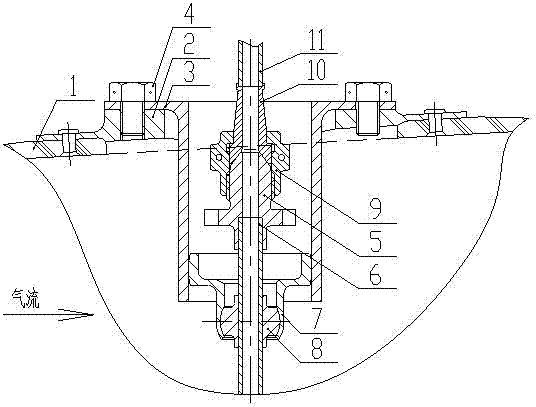
[0017] This embodiment provides a tooth-shaped floating seal structure for passing through the casing, which is characterized in that it includes a casing 1, a casing mounting seat 2, a lead-out pipe sleeve 3, bolts 4, an outer cone joint 5, Conduit 6, ball seat 7, ball head 8, extra nut 9, flat nozzle 10, conduit 11;

[0018] Among them: the outer cone joint 5 and the conduit 6 are welded together, which is the casing inner conduit assembly; the external nut 9, the flat nozzle 10, and the conduit 11 are welded together, which is the casing outer conduit assembly, and the casing mounting seat 2 is welded or riveted On the casing 1, the lead-out tube sleeve 3 is fixed on the casing mounting seat 2 through six bolts 4, and is closed through the ball head seat 7, so that it is assembled with the ball head 8, and the ball head seat 7 is opposite to the ball head The head 8 can freely rotate in all directions within the allowable space range, and the ball head 8 is welded on the co...

Embodiment 2

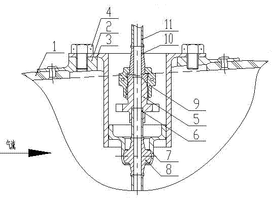
[0027] This embodiment provides a tooth-shaped floating seal structure for passing through the casing, which is characterized in that it includes a casing 1, a casing mounting seat 2, a lead-out pipe sleeve 3, bolts 4, an outer cone joint 5, Conduit 6, ball seat 7, ball head 8, extra nut 9, flat nozzle 10, conduit 11;

[0028] Among them: the outer cone joint 5 and the conduit 6 are welded together, which is the casing inner conduit assembly; the external nut 9, the flat nozzle 10, and the conduit 11 are welded together, which is the casing outer conduit assembly, and the casing mounting seat 2 is welded or riveted On the casing 1, the lead-out tube sleeve 3 is fixed on the casing mounting seat 2 by 8 bolts 4, and closed by the ball head 7 to make it integrated with the ball head 8, and the ball head 7 is opposite to the ball head 8 can freely rotate in all directions within the allowed space range, and the ball head 8 is welded on the conduit 6 .

[0029] There is a tighteni...


PUM


Abstract

A sleeve-tooth-shaped floating sealing structure penetrating a casing is characterized by comprising the casing, casing mounts, transfer pipe sleeves, bolts, an external cone connector, a guide pipe, a ball joint housing, a ball joint, a captive nut, a flat nozzle and a guide pipe. The external cone connector and the guide pipe are integrated to be a guide pipe assembly inside the casing; the captive nut, the flat nozzle and the guide pipe are integrated by welding to be a guide pipe assembly outside the casing; the casing mounts are connected on the casing by welding or riveting; the transfer pipe sleeves are fixed on the casing mounts through bolts ,and closed up through the ball joint housing to be integrated with the ball joint; the ball joint housing can freely rotate corresponding to the ball joint in all directions within an allowed spacial range; and the ball joint is welded on the guide pipe. The sleeve-tooth-shaped floating sealing structure penetrating the casing has the advantages that the sealing structure is mainly designed for pipelines penetrating the casing on aero-engines, and the sealing structure with diameter of phi 6-phi 12 improves product performance, improves assemblability and tightness of the casing and the pipelines, and reduces assembly stress of the pipelines.

Description

technical field [0001] The invention relates to the field of sealing structures of aero-engines, and in particular provides a gear-shaped floating sealing structure for passing through casings. Background technique [0002] The pipes passing through the casing on traditional engines adopt different sealing structures according to their diameters and transmission media. Generally, pipelines with a diameter of φ6~φ12 adopt an integrated seal structure passing through the casing, that is, the joints on the pipeline in the casing are exposed outside the casing, and the half-type floating ring and the inner hole of the casing mounting seat (or independent sleeve) fit. This sealing structure is simple to fix and reliable in sealing, but requires the casing to be a split structure. There are often multiple pipes with different axial and angular positions on the engine passing through the casing. Therefore, when the casing is assembled, the mounting holes of the casing need to be ...

Claims


Application Information

Patent Timeline
Patent Type & Authority Patents(China)
IPC IPC(8): F16L5/02
CPCF16L5/025F16L19/025
Inventor 贾铎安喆高东武朱峰
Owner AECC SHENYANG ENGINE RES INST
Why Eureka
Try Eureka