Heat pipe solar thermal collector

A solar heat collector and heat pipe technology, applied in the field of solar heat collectors, can solve the problems of leakage at the welding place, discount of heat conduction efficiency, complicated and time-consuming assembling method of heat pipe solar heat collector 1a, etc., so as to simplify the combination method. , good heat collection effect, increase practical effect

Active Publication Date: 2013-05-08
KUNSHAN JUZHONG ELECTRONICS
View PDF7 Cites 1 Cited by
  • Summary
  • Abstract
  • Description
  • Claims
  • Application Information

AI Technical Summary

Problems solved by technology

[0005] The assembling method of the above-mentioned heat pipe solar collector 1a is not only complicated and time-consuming, but also has the possibility of leakage at the weld. In addition, since these heat pipes 30a do not directly contact the water in the heat exchange pipe body 10a when exchanging heat, Instead, it is indirectly conducted into the heat exchange tube body 10a through the branch pipes 20a, so the heat conduction efficiency is greatly reduced and needs to be improved.

Method used


Image

  • Heat pipe solar thermal collector
  • Heat pipe solar thermal collector
  • Heat pipe solar thermal collector

Examples


Embodiment Construction

[0057] The detailed description and technical content of the present invention are described below with accompanying drawings. However, the attached drawings are provided for reference and illustration only, and are not intended to limit the present invention.

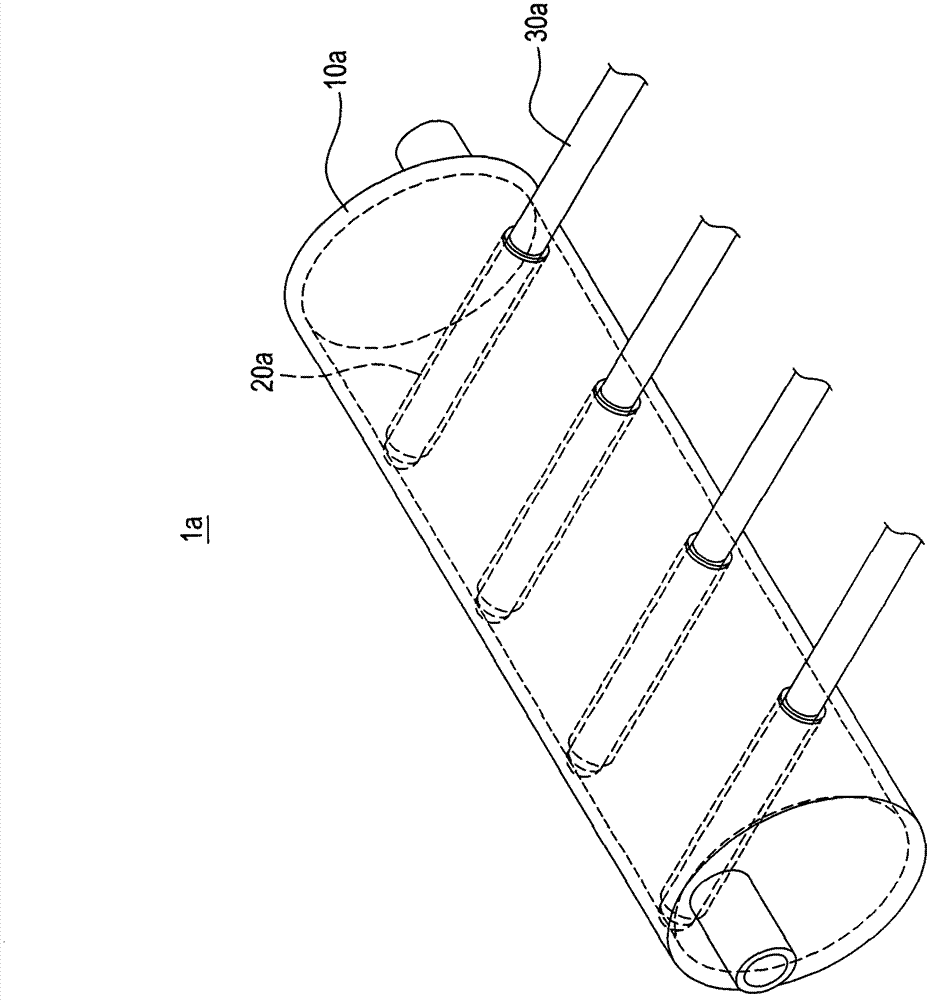
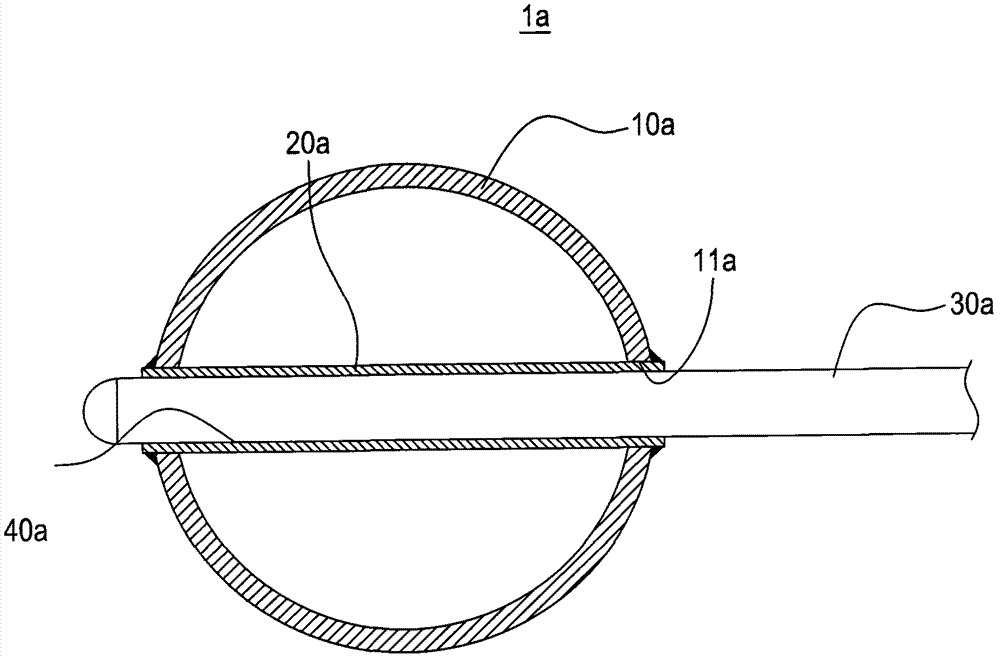
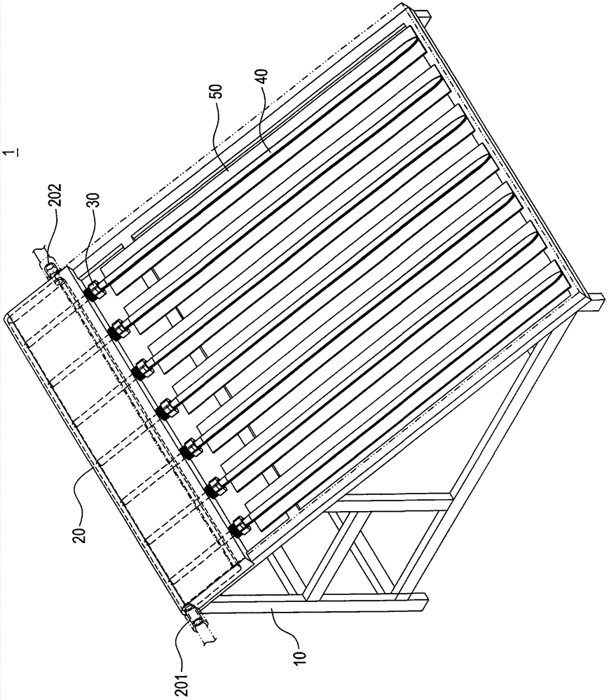
[0058] Please refer to image 3 , is a schematic diagram of the use of the heat pipe solar collector of the present invention; the heat pipe solar collector 1 of the present invention (hereinafter referred to as the collector) includes a heat collecting frame 10, a heat exchange pipe body 20, a connecting sleeve The barrel 30 , at least one heat pipe 40 , and at least one heat collecting plate 50 .

[0059]In this embodiment, the heat collecting frame 10 is a triangular frame, but it is not limited thereto. The heat exchanging tube body 20 and the heat pipe 40 are fixed on the heat collecting frame 10, and the heat exchanging tube The body 20 is arranged at a height of the heat collecting frame 10 .

[0060] Please a...


PUM


Abstract

The invention discloses a heat pipe solar thermal collector. The heat pipe solar thermal collector comprises a heat exchange tube body, a penetration sleeve and at least one heat pipe. The heat exchange tube body is provided with a tube wall and an accommodation space enclosed by the tube wall. An open groove not penetrating through the tube wall is formed on one end face of the tube wall. First threads are arranged on the inner wall surface of the open groove. At least one through hole communicated with the accommodation space is formed in the open groove. The penetration sleeve comprises a pipe column with a penetration hole. The pipe column is provided with second threads, and is connected into the open groove through the threads. Each heat pipe comprises a body and working fluid in the body. One end of each heat pipe penetrates through the penetration hole and the corresponding through hole to be arranged in the accommodation space. The heat of the heat pipes can be taken away by cold water flowing into the heat exchange tube body to realize the heat exchange of the heat pipes by the phase changes of the working fluid. Therefore, an assembly mode for the thermal collector is simplified, and a thermal collection effect is improved.

Description

technical field [0001] The invention relates to a solar heat collector, in particular to a heat pipe type solar heat collector. Background technique [0002] Under the threat of rising awareness of environmental protection and energy crisis, safe and non-polluting solar radiation heat energy has gradually been widely accepted by the public, but how to effectively and fully convert and apply solar radiation heat energy is the long-term struggle of the present invention. question. At present, in the application of solar radiant heat energy, solar collectors are relatively commercial products with economic benefits. In order to improve the conversion efficiency of solar radiant heat energy, heat pipes with excellent thermal conductivity are applied to solar collectors as a transfer Thermal components have achieved good results. [0003] Please refer to figure 1 and figure 2 , which are the schematic diagram and cross-sectional view of the current heat pipe solar collector;...

Claims


Application Information

Patent Timeline
Patent Type & Authority Applications(China)
IPC IPC(8): F24J2/32F24J2/46F24S10/70F24S10/95
CPCF24J2/32F24J2/46Y02E10/44F24J2/345F24J2/055F24J2/24F24S10/45F24S10/95F24S60/30
Inventor 郭大祺汪学海龙玲
Owner KUNSHAN JUZHONG ELECTRONICS
Why Eureka
Try Eureka