
Magnet ring winding machine

A technology of winding and winding mechanism, applied in coil manufacturing, electromechanical devices, control of mechanical energy, etc., can solve the problems of high cost, uneven quality and low efficiency of magnetic coils, so as to reduce production costs and improve stability. , the effect of improving production efficiency

Inactive Publication Date: 2013-05-08
陈登儒
View PDF5 Cites 14 Cited by
  • Summary
  • Abstract
  • Description
  • Claims
  • Application Information

AI Technical Summary

Problems solved by technology

[0002] At present, the scope of application of magnetic ring induction coils is very wide. There are many magnetic winding machines on the market. The diameter of the wire wound by the common magnetic winding machines in these markets is generally relatively thin. For the winding of thicker wires, The traditional manual method is still used. The cost of manual winding of the magnetic ring is high, the efficiency is low, and it is difficult to control the quality of the product, and it is prone to uneven quality. It will affect the quality of electronic products when applied to electronic products. Stability and service life

Method used


Image

  • Magnet ring winding machine
  • Magnet ring winding machine
  • Magnet ring winding machine

Examples


Embodiment Construction

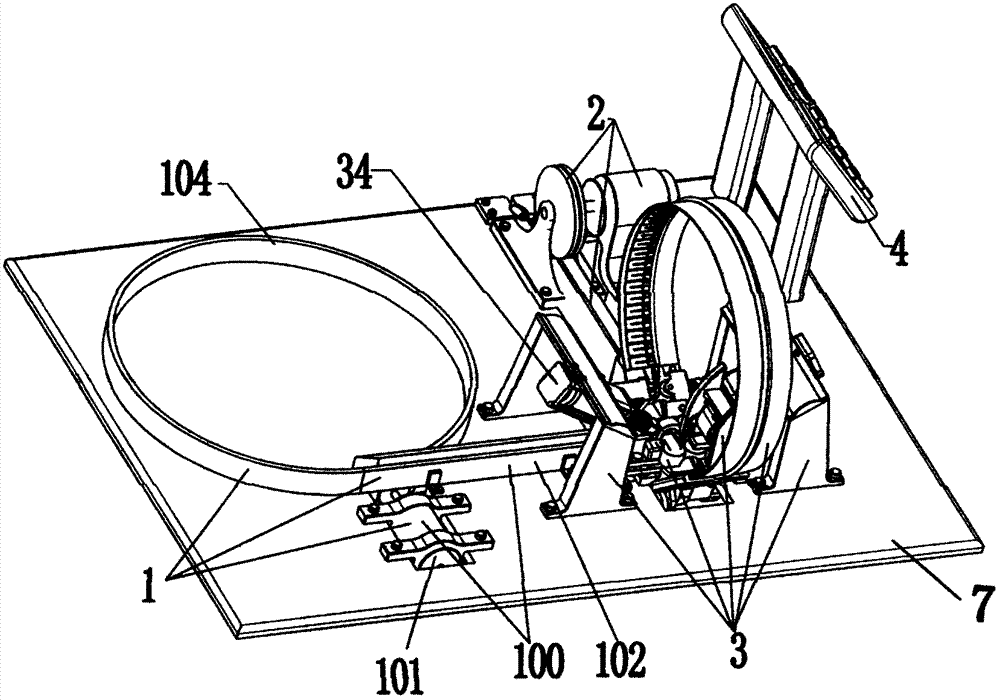
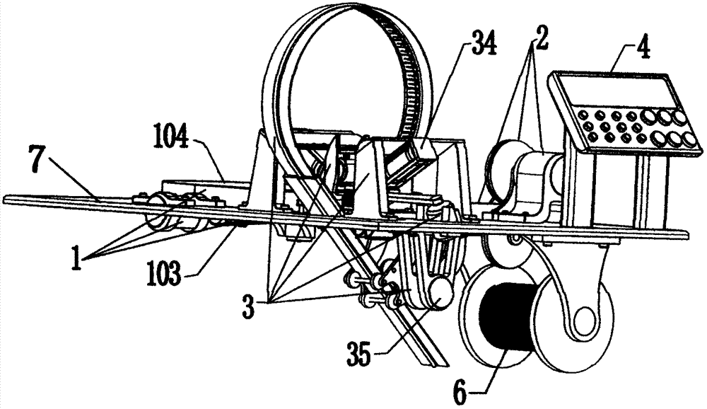
[0031] see figure 1 , figure 2 , image 3 , Figure 4 , Figure 5 , Image 6 , Figure 7 , Figure 8 , Figure 9 , Figure 10 , Figure 11 , under the control of the console 4, the wire driving device 32 in the winding mechanism 3 works, wherein, the stepping motor 32a1 of the wire pulling device 32a on the guide seat 312 rotates, and the belt 32a3 is connected to the pulley 32a2 on the stepping motor 32a1 and The belt pulley 32a4 on the driving wheel 32a5 makes the driving wheel 32a5 run, and the driven wheel 32a6 installed on the support 32a7 of the "H" shape is next to the driving wheel 32a5 under the active force of the spring 32a8 on the support seat 32a9. Under the operation of 32a5, a pulling force is formed; the stepping motor 32b1 of the wire transmission device 32b on the base 311 rotates, and the belt 32b3 connects the pulley 32b2 on the stepping motor 32b1 and the pulley 32b4 on the driving pulley 32b5 to make the driving pulley 32b5 run. The driven whee...


PUM


Abstract

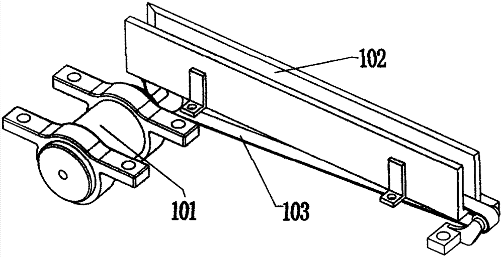
The invention discloses a magnet ring winding machine used for wire rod winding magnet rings with thick wire diameters. The magnet ring winding machine comprises a magnet ring conveying mechanism, a wire feeding mechanism, a winding mechanism and an operating table, wherein the magnet ring conveying mechanism is arranged in the middle of one side of the winding mechanism and comprises a vibration disk and a magnet ring conveying device, and the magnet ring conveying device is arranged between the vibration disk and the winding mechanism; the wire feeding mechanism is arranged behind a base of the winding mechanism and comprises a stepper motor, an upper wire feeding wheel arranged on a rotating shaft of the stepper motor, a lower wire feeding wheel arranged on an internally arranged bearing below the upper wire feeding wheel, a wire horn mouth arranged behind the upper wire feeding wheel and the lower wire feeding wheel, and a wire conduit communicated with a wire hole in the base of the winding mechanism; and the winding mechanism comprises a wire device guiding wire rods to operate, the base mounted on the wire device, a wire driving device mounted on a guide seat, a magnet ring control device fixing and driving a magnet ring to rotate, a wire lifting device arranged on the guide seat, and a wire groove soft belt pulling device arranged below the guide seat.

Description

technical field [0001] The invention relates to a device for winding and processing an inductance coil with a magnetic core in a ring shape, in particular to a winding machine for a magnetic ring inductance coil. Background technique [0002] At present, the scope of application of magnetic ring induction coils is very wide. There are many magnetic winding machines on the market. The diameter of the wires wound by the common magnetic winding machines in these markets is generally relatively thin. For the winding of thicker wires, The traditional manual method is still used. The cost of manual winding of the magnetic ring is high, the efficiency is low, and it is difficult to control the quality of the product, and it is prone to uneven quality. It will affect the quality of electronic products when applied to electronic products. stability and service life. Contents of the invention [0003] The purpose of the present invention is to overcome the problems of the prior art...

Claims


Application Information

Patent Timeline
IPC IPC(8): H01F41/08H02K7/116
Inventor 陈登儒
Owner 陈登儒
Learn More