Transverse laminated synchronous reluctance motor with auxiliary permanent magnets

A technology of synchronous reluctance motor and permanent magnet, which is applied in the direction of synchronous motor with stationary armature and rotating magnet, magnetic circuit shape/style/structure, magnetic circuit rotating parts, etc., and can solve the problem of narrow constant power speed regulation range , low power factor and other issues, to achieve the effect of widening the constant power speed regulation range, strong magnetic resistance torque, and high salient pole ratio

Active Publication Date: 2013-05-08
SHANGHAI FUTIAN ELECTRIC TECH
View PDF6 Cites 14 Cited by
  • Summary
  • Abstract
  • Description
  • Claims
  • Application Information

AI Technical Summary

Problems solved by technology

[0004] Aiming at the defects and deficiencies in the prior art, the present invention proposes a transverse laminated synchronous reluctance motor with auxiliary permanent magnets to solve the problems of low power factor and constant power regulation of synchronous reluctance motors existing in the prior art. Technical problem with narrow speed range

Method used


Image

  • Transverse laminated synchronous reluctance motor with auxiliary permanent magnets
  • Transverse laminated synchronous reluctance motor with auxiliary permanent magnets
  • Transverse laminated synchronous reluctance motor with auxiliary permanent magnets

Examples


Embodiment Construction

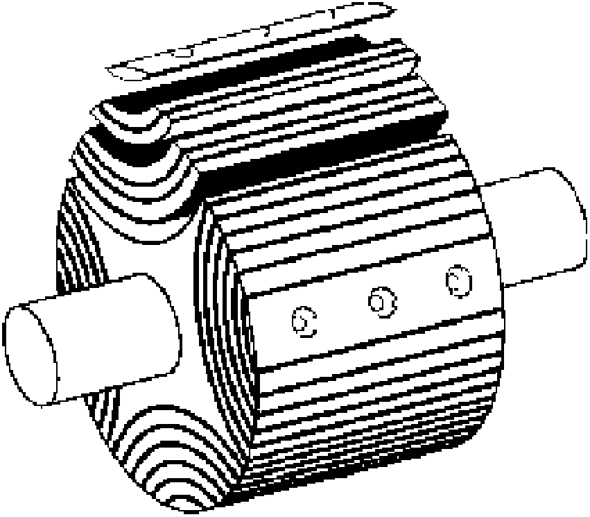
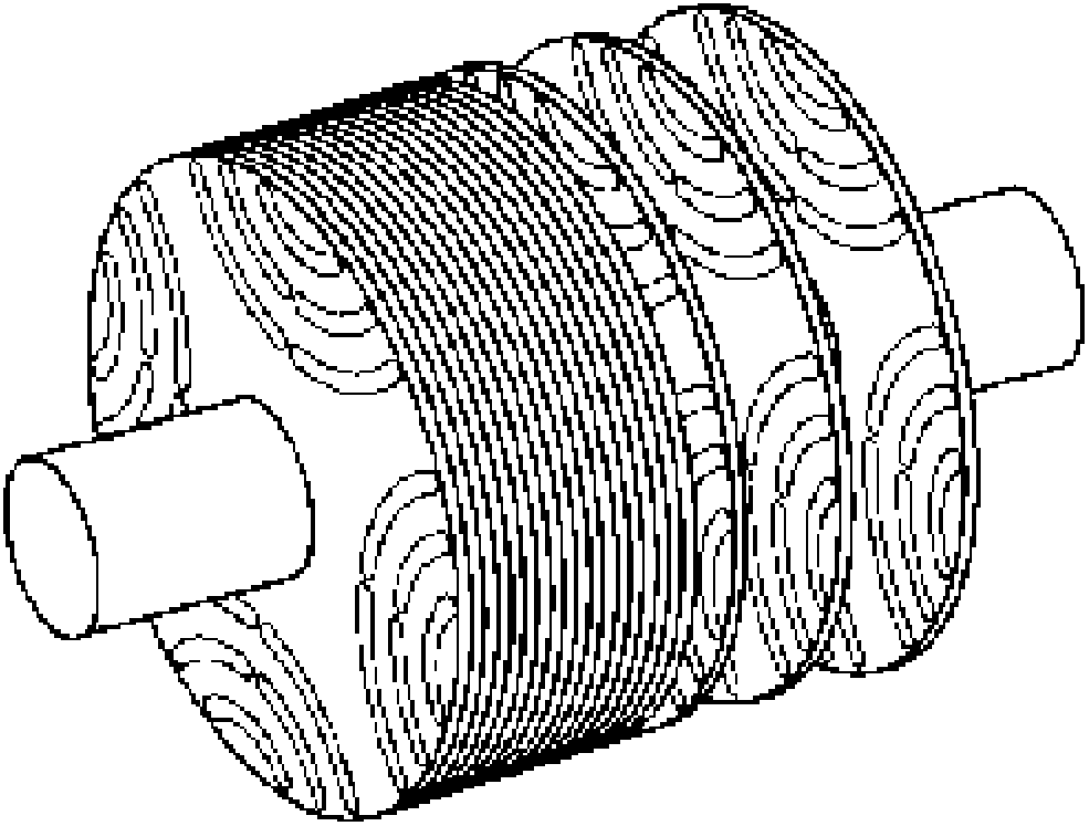
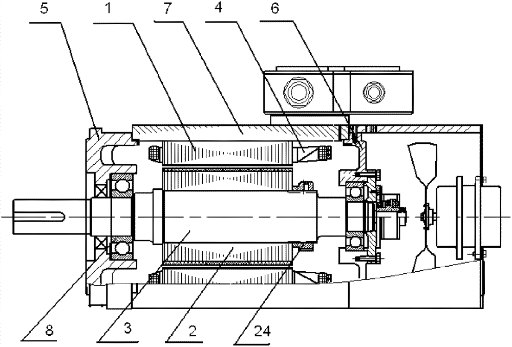
[0020] The horizontal laminated synchronous reluctance motor with auxiliary permanent magnet of the present invention is specifically as Figure 2-4 As shown, it includes a stator core 1, a stator winding 4, a rotor core assembly 2, a rotating shaft 3, a bearing 8 supporting the rotating shaft 3, a front end cover 5, a rear end cover 6 and a casing 7, wherein,

[0021] The rotor core assembly 2 includes a rotor core 21 sleeved on the rotating shaft 3 and a plurality of block-shaped permanent magnets 22. The rotor core 21 is formed by laminating multiple complete steel sheets with a single shape laterally along the rotating shaft 3. The rotor core 21 has multiple layers of arc slots 23 suitable for inserting block permanent magnets 22;

[0022] The block permanent magnet 22 is arranged in the above-mentioned arc groove 23, and the polarity of each permanent magnet 22 in each layer of arc groove 23 under the same pole is the same and forms a magnetic pole group, and the polarity...


PUM


Abstract

The invention discloses a transverse laminated synchronous reluctance motor with auxiliary permanent magnets. The transverse laminated synchronous reluctance motor with the auxiliary permanent magnets comprises a stator core, stator windings, a rotor core assembly, a rotating shaft, a bearing used for supporting the rotating shaft, a front end cover, a rear end cover and a machine shell. The rotor core assembly comprises the rotor core and a plurality of block-shaped permanent magnets, wherein the rotor core and the plurality of block-shaped permanent magnets are sleeved on the rotating shaft. The rotor core is formed by transversely laminating a plurality of single-shaped complete steel sheets along the rotating shaft. The rotor core is provided with a plurality of layers of arc grooves suitable for insertion of the blocked-shaped permanent magnets. The block-shaped permanent magnets are arranged in the arc grooves. The polarities of the permanent magnets in the layers of arch grooves of the same polar are the same and form a magnetic pole group. The polarities of magnetic pole sets of two adjacent poles are opposite. According to the synchronous reluctance motor, the auxiliary block-shaped permanent magnets are arranged in the arc grooves of the rotor core, and therefore power factors of the motor are improved, and constant power speed adjustable ranges of the motor are widened; and due to the fact that the rotor core is formed by transversely laminating the plurality of single-shaped complete silicon steel sheets, the motor can have good mechanical strength.

Description

technical field [0001] The invention relates to a synchronous reluctance motor, in particular to a transverse laminated synchronous reluctance motor with auxiliary permanent magnets. Background technique [0002] Synchronous reluctance motor has gradually attracted people's research interest in recent years because of its simple structure, no electromagnetic loss in the rotor, and the ability to avoid the shortcomings of switched reluctance motors such as large noise and significant torque ripple at low speeds. The specific structure of the rotor and its performance during operation determine the performance of the synchronous reluctance motor during operation. The synchronous reluctance motor in the prior art has the disadvantages of low power factor and narrow constant power speed regulation range. This is because the rotor of the synchronous reluctance motor has no excitation permanent magnet, and there will be a large excitation current component in the stator current. ...

Claims


Application Information

Patent Timeline
Patent Type & Authority Applications(China)
IPC IPC(8): H02K21/14H02K1/27
Inventor 陶骏郁薇英
Owner SHANGHAI FUTIAN ELECTRIC TECH
Why Eureka
Try Eureka