Signal generator

A signal generator and signal technology, applied in the direction of pulse generation, pulse technology, electrical components, etc., can solve problems such as cable and pipeline positioning, high-frequency signal dissipation, etc. that are not suitable for general

Active Publication Date: 2019-07-16
雷迪有限公司
View PDF4 Cites 0 Cited by
  • Summary
  • Abstract
  • Description
  • Claims
  • Application Information

AI Technical Summary

Problems solved by technology

Dedicated single-frequency locators optimized for finding telecommunication cables exist, but these are poorly suited for general cable and pipe locating, as high frequency signals are rapidly dissipated along typical cable or pipe distances

Method used


Image

  • Signal generator
  • Signal generator
  • Signal generator

Examples


Embodiment Construction

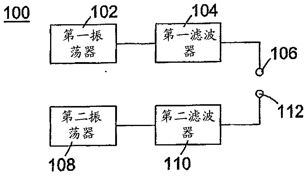
[0035] figure 1 A signal generator 100 is shown which generates an AC signal for coupling to a buried conductor. The signal generated by the signal generator 100 has two frequencies, a first frequency of 33 kHz and a second frequency of 66 kHz. The signal generator has a first oscillator 102 which generates an AC signal with a frequency of 33 kHz. The first oscillator is connected to a first filter 104 configured to pass a signal having a frequency of 33 KHz and attenuate any harmonics generated by the first oscillator. A first terminal 106 is connected to said first filter 104 . The signal generator 100 has a second oscillator 108 which generates a signal with a second frequency. In this example, the second frequency is 66kHz. The second oscillator is connected to a second filter 110 . The second filter 110 allows signals having a frequency of about 66 kHz to pass and attenuates harmonics. Said second filter 110 is connected to a second terminal 112 of the signal genera...


PUM


Abstract

A signal generator for coupling to a concealed conductor, the signal generator comprising: a first oscillator configured to generate a first waveform having a first frequency; a first terminal passing through a first bandpass filter connected to the first oscillator, the first bandpass filter configured to pass a signal of the first frequency; a second oscillator configured to generate a second waveform having a second frequency; and a second terminal connected to the second oscillator through a second bandpass filter configured to pass signals of the second frequency.

Description

technical field [0001] The present application relates to signal generators for detecting current-carrying conductors. Background technique [0002] Before starting excavation or other construction where electrical cables, fiber optic cables, or other utility pipes or conduits are buried, it is important to determine the location of these buried cables or conduits to ensure that they are not damaged during construction. It is also useful to be able to trace the path of buried cables or conduits. Current-carrying conductors emit electromagnetic radiation that can be detected by an electromagnetic antenna. If fiber optic cables or non-metallic utility pipes or conduits are fitted with small electronic trace wires, alternating currents can be coupled in the trace wires, thereby radiating electromagnetic radiation. The use of detectors to detect electromagnetic fields emitted by conductors carrying alternating current is known. [0003] A type of such detector operates in one...

Claims


Application Information

Patent Timeline
Patent Type & Authority Patents(China)
IPC IPC(8): H03K4/02
Inventor 理查德·戴维·皮尔逊路易吉·朗弗朗希
Owner 雷迪有限公司
Why Eureka
Try Eureka