Interconnection assembly for data communication

a technology of data communication and interconnection assembly, which is applied in the direction of waveguides, particular array feeding systems, coupling device connections, etc., can solve the problems of comparatively high cost of sfp-modules, achieve low cost, reduce power loss, impedance and signal reflection, and facilitate alignment of at least one cable

Active Publication Date: 2020-07-02
HUBERSUHNER AG
View PDF0 Cites 0 Cited by
  • Summary
  • Abstract
  • Description
  • Claims
  • Application Information

AI Technical Summary

Benefits of technology

[0008]In a variation, the second port is funnel-shaped. It was found that this reduces signal reflection, power loss and impedance at the site of signal transfer between the cable core and the hollow conductor. The second port having a funnel shape maintains alignment of the cable core with the section of the hollow conductor extending at least partially along the upper face of the first plate element.
[0009]The core of the at least one cable may extend beyond the jacket at a cable end, thereby facilitating direct signal transfer between the cable core and the hollow conductor resulting in reduced power loss, impedance and signal reflection. In a variation, the core of the at least one cable reaches into the second port of the hollow conductor.
[0010]The second connector part may comprise a cable insertion rack compri

Problems solved by technology

One cost driving factor is that each optical line needs an SFP-Module (Sma

Method used


Image

  • Interconnection assembly for data communication
  • Interconnection assembly for data communication
  • Interconnection assembly for data communication

Examples


Embodiment Construction

[0033]Reference will now be made in detail to certain embodiments, examples of which are illustrated in the accompanying drawings, in which some, but not all features are shown. Whenever possible, like reference numbers will be used to refer to like components or parts.

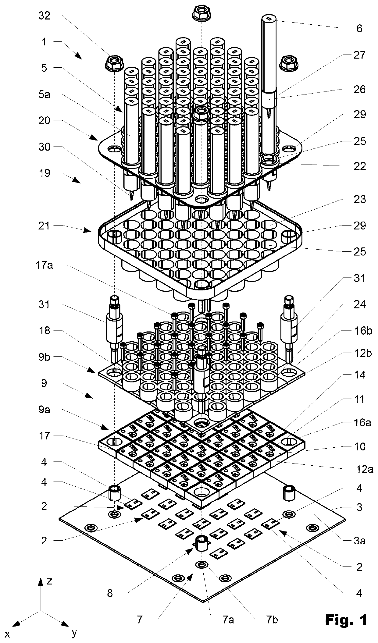
[0034]FIG. 1 shows an interconnection assembly 1 for connecting an array of chips 2, on which antennae 4 are mounted, to a plurality of cables 5. The chips 2, for example MMICs (Monolithic Microwave Integrated Circuit), are mounted on a PCB 3. The antennae 4 are foreseen to send and receive, to and from the cables 5, signals of up to 140 GHz. The cables 5 are dielectric waveguides each comprising a cable core 6 surrounded by a cable jacket 5a whereby the cable core 6 and cable jacket 5a have differing refractive indexes. The PCB 3 comprises a plurality of alignment structures 7 surrounding bores 7a in the PCB 3, wherein each bore 7a is surrounded by a liquefiable, in particular solderable material 7b such as metal or ...


PUM


Abstract

An interconnection assembly for a switching device includes at least one cable with a core having a first dielectric material, wherein the core is at least partially surrounded by a second dielectric material having a refractive index different from the first dielectric material. A first connector part is positioned with respect to at least one antenna and includes a fan-out element and at least one hollow conductor arranged between the antenna and the core of the cable wherein the at least one hollow conductor extends in the fan-out element to guide a signal between the antenna and the core of the cable, wherein the hollow conductor includes a first port aligned with the antenna and a second port, and when assembled is in communication with the core of the cable. At least one second connector part is interconnected to the cable positioning the core of the cable in a connected position with respect to the second port of the hollow conductor.

Description

BACKGROUND OF THE INVENTIONField of the Invention[0001]The present invention relates to an interconnection assembly according to the preamble of patent claims.Discussion of Related Art[0002]For interconnecting switches, optical transmission lines are used for best performance. One cost driving factor is that each optical line needs an SFP-Module (Small Form-factor-Pluggable-Module)). The SFP-Module is a compact optical module transceiver used for both telecommunication and data communications applications. SFP-Modules are comparatively expensive.SUMMARY OF THE INVENTION[0003]It is an object of the invention to provide an improved way to transfer data between at least two electronic devices in a server room or the like, namely switches, servers, etc., in particular on the principle of the dielectric waveguide.[0004]According to the invention, an interconnection assembly, such as for a switching device in a server room, comprises at least one cable with a core made from a first dielec...

Claims


Application Information

Patent Timeline
IPC IPC(8): H01R12/75H01Q1/38H01Q1/22H04Q11/00H01R13/512H01R13/518
CPCH04Q11/0005H01R2201/02H04Q2011/0052H01Q1/38H01R13/518H01Q1/2283H01R13/512H01R12/75H01P3/16H01Q21/0025H01Q21/0068H01Q19/08H01Q21/064H01Q21/06H01Q21/00H01Q13/24
Inventor HÜGEL, ULF
Owner HUBERSUHNER AG
Why Eureka
Try Eureka