Slip ring device

a technology of ring device and ring, which is applied in the manufacture of slip-rings, current collectors, coupling device connections, etc., can solve the problems of increasing signal attenuation, reducing reliability, and not smoothly transmitting through signal transmission routes

Inactive Publication Date: 2013-02-19
NIDEC SERVO CORP
View PDF7 Cites 8 Cited by
  • Summary
  • Abstract
  • Description
  • Claims
  • Application Information

AI Technical Summary

Benefits of technology

[0009]Two or more of the lead lines electrically connected to the electricity-collecting rings of the electricity-collecting body include twisted-pair lines (preferably including shielding). This makes it possible to make the signals transmitted through the lead lines less susceptible to noises, thereby reducing the amount of radiating noises. If the impedance of the twisted-pair lines is matched with the impedance of slip rings as close as possible, it is possible to reduce reflection of signals caused by the mismatching of impedances and to reduce degradation of signals. As a result of this specific arrangement, it becomes possible to transmit high-speed high-frequency signals, such as, for example, image signals of a high-definition camera. Accordingly, the slip ring device can be included in, for example, a high-definition monitoring camera or other suitable apparatus. The above and other elements, features, steps, characteristics and advantages of the present invention will become more apparent from the following detailed description of the preferred embodiments with reference to the attached drawings.

Problems solved by technology

Therefore, high-speed high-frequency signals such as image signals of a high-definition camera are reflected in the joints of the signal transmission routes and thus are not smoothly transmitted through the signal transmission routes.
This leads to increased signal attenuation and reduced reliability.

Method used


Image

  • Slip ring device
  • Slip ring device
  • Slip ring device

Examples


Embodiment Construction

[0016]A slip ring device according to preferred embodiments of the present invention will now be described with reference to the accompanying drawings.

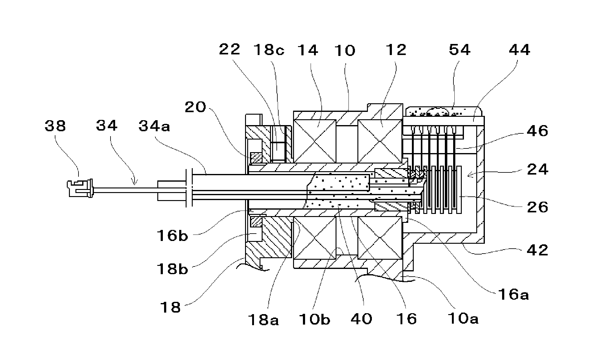
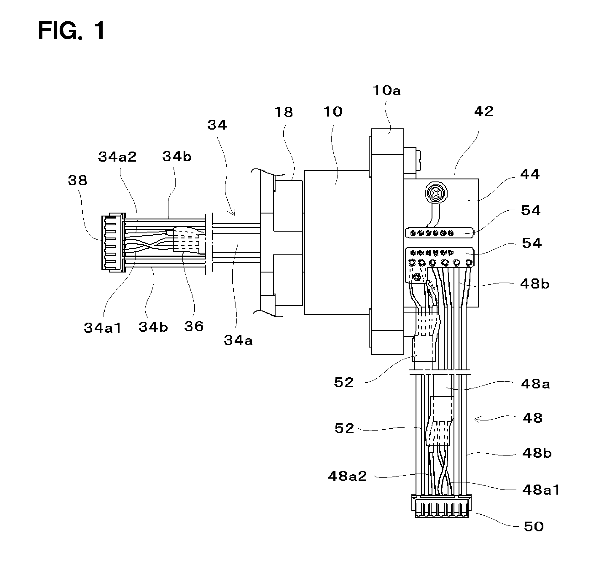
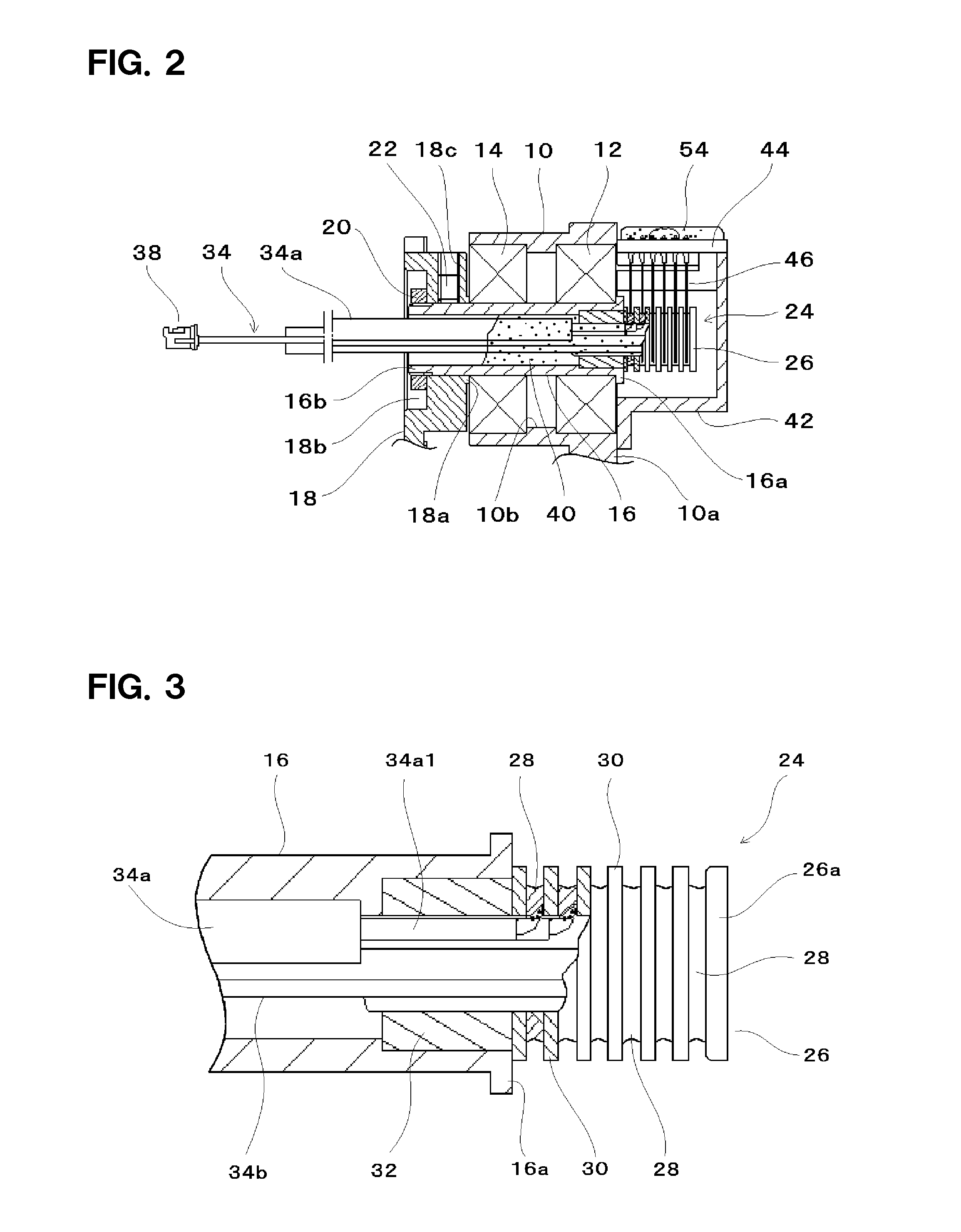
[0017]FIGS. 1 and 2 show the overall configuration of a slip ring device. A cylindrical pipe-shaped shaft 16 is rotatably supported inside a tubular body 10 of a main case through bearings 12 and 14, which are preferably defined by a pair of, for example, ball bearings. An attachment flange 10a arranged to permit attachment of the slip ring device is provided at the outer circumference of one end portion of the tubular body 10 as a single monolithic piece. An annular positioning shoulder portion 10b is provided in a middle area of an inner circumferential surface of the tubular body 10 so as to protrude radially inwards. The bearings 12 and 14 are preferably mounted to the tubular body 10 with the end surfaces of outer races thereof brought into contact with the annular shoulder portion 10b.

[0018]An annular flange portion 16a is prov...


PUM


Abstract

A slip ring device includes a hollow pipe-shaped shaft rotatably supported inside a tubular body of a main case through a bearing and an electricity-collecting body integrally and concentrically provided in the shaft. The electricity-collecting body preferably includes a plurality of electricity-collecting rings and a plurality of insulating rings alternately layered with one another. The slip ring device further includes a plurality of brushes held by the main case and tip end portions making sliding contact with outer circumferential surfaces of the electricity-collecting rings and a plurality of lead lines introduced into the shaft. The lead lines include tip end portions electrically connected to the respective electricity-collecting rings. Two or more of the lead lines include shielded lines.

Description

BACKGROUND OF THE INVENTION[0001]1. Field of the Invention[0002]The present invention relates to a slip ring device and more specifically to a slip ring device preferably for use in transmitting signals in a mechanism including a swing unit, such as, for example, a monitoring camera or a robot mechanism.[0003]2. Description of the Related Art[0004]A conventional slip ring device extensively used in flexing portions or rotating portions such as joint portions of an industrial robot can maintain connection and electric conduction between a fixed-side wiring line and a rotating-side wiring line at all times regardless of continuous rotation or reverse rotation. The slip ring device is designed to avoid disconnection of a wiring line otherwise caused by complex layout or bending fatigue. More specifically, as shown in FIGS. 11 and 12 of Japanese Patent Application Publication No. 2003-116249, a known slip ring device includes a rotating shaft unit having a rotating shaft and a plurality...

Claims


Application Information

Patent Timeline
Patent Type & Authority Patents(United States)
IPC IPC(8): H01R39/00
CPCH01R13/6473H01R39/64H01R13/6463H01R39/34H01R43/10H01R2107/00
Inventor YAMAMOTO, ATSUSHIENDO, KAORU
Owner NIDEC SERVO CORP
Why Eureka
Try Eureka