Method and user equipment and base station for transmission and control information

A technology of transmission control and modulation symbols, applied in the field of transmission control information, can solve the problems of high transmission power, waste of transmission power of user equipment, and low power utilization efficiency

Active Publication Date: 2013-05-08
HUAWEI TECH CO LTD
View PDF4 Cites 39 Cited by
  • Summary
  • Abstract
  • Description
  • Claims
  • Application Information

AI Technical Summary

Problems solved by technology

[0008] However, in order to meet the performance target for the UCI with higher performance target requirements, the user equipment uses a higher transmission power when sending UCI, but for the UCI with lower performance target ...

Method used


Image

  • Method and user equipment and base station for transmission and control information
  • Method and user equipment and base station for transmission and control information
  • Method and user equipment and base station for transmission and control information

Examples


Embodiment 1

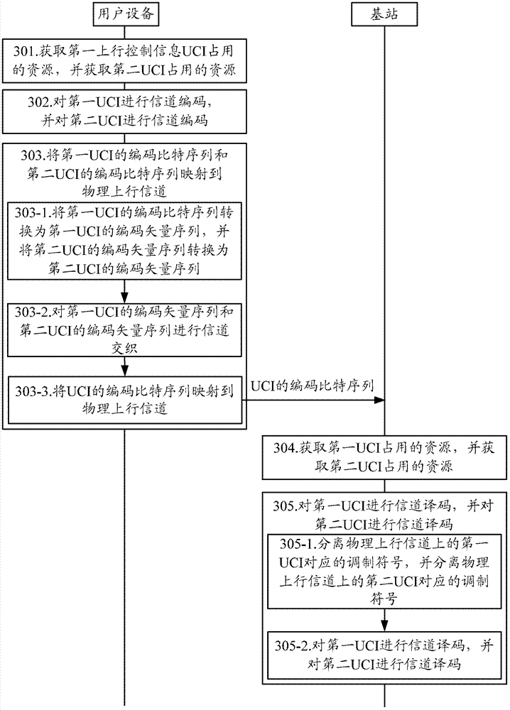
[0094] image 3 is a schematic flowchart of the process of transmitting control information according to an embodiment of the present invention.

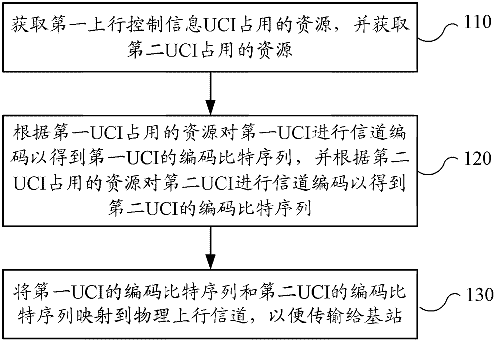
[0095] In step 301, the UE acquires resources occupied by the first uplink control information UCI, and acquires resources occupied by the second UCI.

[0096] For example, in the LTE-A (Long Term Evolution-Advanced, Advanced Long Term Evolution) carrier aggregation scenario, it will appear that the channel state information (Channel State Information, CSI) and hybrid automatic retransmission confirmation information need to be reported on an uplink subframe at the same time (Hybrid Automatic Repeat request-Acknowledgment, HARQ-ACK). CSI includes periodic CSI and aperiodic CSI. The periodic CSI includes channel quality indicator (Channel quality indicator, CQI), precoding matrix indicator (Precoding Matrix indicator, PMI), rank indicator (Rank Indication, RI), precoding type indicator (Precoding type indicator, PTI) and other info...

Embodiment 2

[0184] In Embodiment 1, when the UE simultaneously maps the first UCI and the second UCI to the physical uplink channel for transmission, the second UCI punctures the first UCI. In the second embodiment, the first UCI and the second UCI are simultaneously mapped to the physical uplink channel for transmission by performing rate matching on the first uplink UCI according to the resources occupied by the second UCI.

[0185] There are two differences between embodiment two and embodiment one:

[0186] One is the resource Q' occupied by the first UCI in each mode in step 301 of the first embodiment CSI =Q'-Q' HARQ-ACK ;

[0187] The second is that step 303-2 in the first embodiment encodes the vector sequence of the first UCI and the encoded vector sequence of the second UCI When channel interleaving is performed, the coded vector sequence of the second UCI needs to be Write the matrix, and then encode the vector sequence of the first UCI Write matrix, then in the step ...

Embodiment 3

[0202] Embodiment 1 and Embodiment 2 both map the second UCI to all time-domain SC-FDMA symbols for transmission. In Embodiment 3, only the second UCI is mapped to some time-domain SC-FDMA symbols for transmission, which is applicable to the time-domain SC-FDMA symbols to be transmitted. The number of encoded bits of the second UCI is less and the physical uplink channel for transmitting UCI is as follows Figure 4 or Figure 5 Scene of the structure shown.

[0203] Compared with Embodiment 1 and Embodiment 2, Embodiment 3 is different in that the set of columns in step 303-2 is different. In Embodiment 3, if the physical uplink channel is as Figure 4 As shown in the modified PUCCH format 3, the set of columns is {1, 2}; if the physical uplink channel is as follows Figure 5 For the modified PUCCH format 3 shown, the set of columns is {2, 3} or {1, 4} or {1, 4, 3, 2}.

[0204] For other steps of the third embodiment, reference may be made to the first embodiment, so no det...


PUM


Abstract

The invention discloses a method, user equipment and a base station for transmission and control information. The method includes obtaining resources which are occupied by a first user class identifier (UCI), and obtaining resources which are occupied by a second UCI; conducting channel coding on the first UCI to obtain a coding bit sequence of the first UCI, and conducting channel coding on the second UCI to obtain a coding bit sequence of the second UCI; mapping the coding bit sequence of the first UCI and the coding bit sequence of the second UCI on a physical up channel so as to facilitate transmitting to the base station. The first UCI and the second UCI are independently coded, and corresponding resources of the first UCI and the second UCI are allocated according to performance objectives of different UCIs to ensure respective performance objective requirement of the different UCIs, simultaneously avoid improving transmitting power according to the highest UCI in performance requirement, and improve utilization efficiency of power.

Description

technical field [0001] The embodiments of the present invention relate to the field of wireless communication, and more specifically, to a method for transmitting control information, a user equipment, and a base station. Background technique [0002] LTE-A (Long Term Evolution-Advanced, Advanced Long Term Evolution) is a further evolution and enhanced system of the LTE system. In the LTE-A system, in order to meet the peak data rate requirements of the International Telecommunication Union for the fourth-generation communication technology, the Carrier Aggregation (CA, Carrier Aggregation) technology, also known as the Spectrum Aggregation technology or the Bandwidth Extension (Bandwidth Extension) technology, is introduced. )technology. In carrier aggregation, the frequency spectrum of two or more component carriers (Component Carrier) is aggregated together to obtain a wider transmission bandwidth. The spectrum of each component carrier can be adjacent continuous frequen...

Claims


Application Information

Patent Timeline
IPC IPC(8): H04L1/00
CPCH04L5/00H04L1/18H04W72/1289H04L5/0053Y02B60/50H04L1/0073H04B7/26H04W72/085H04L5/0055H04L1/0026H04L1/0031H04L1/0057H04L1/0059H04L1/1671H04W72/542
Inventor 成艳吕永霞
Owner HUAWEI TECH CO LTD
Why Eureka
Try Eureka