
well

A technology for drilling and wellhead devices, applied in wellbore/well components, measurement, construction, etc., to solve problems such as uncontrollable wells, damage, and impracticality

Active Publication Date: 2020-03-10
METROL TECH
View PDF4 Cites 0 Cited by
  • Summary
  • Abstract
  • Description
  • Claims
  • Application Information

AI Technical Summary

Problems solved by technology

[0012] However, all of the above systems may not actually be practical in the event of an emergency or blowout as there may be no access to the well or the well may not be controllable and the cable and / or data logging equipment may be damaged or destroyed

Method used


Image

  • well
  • well
  • well

Examples


Embodiment Construction

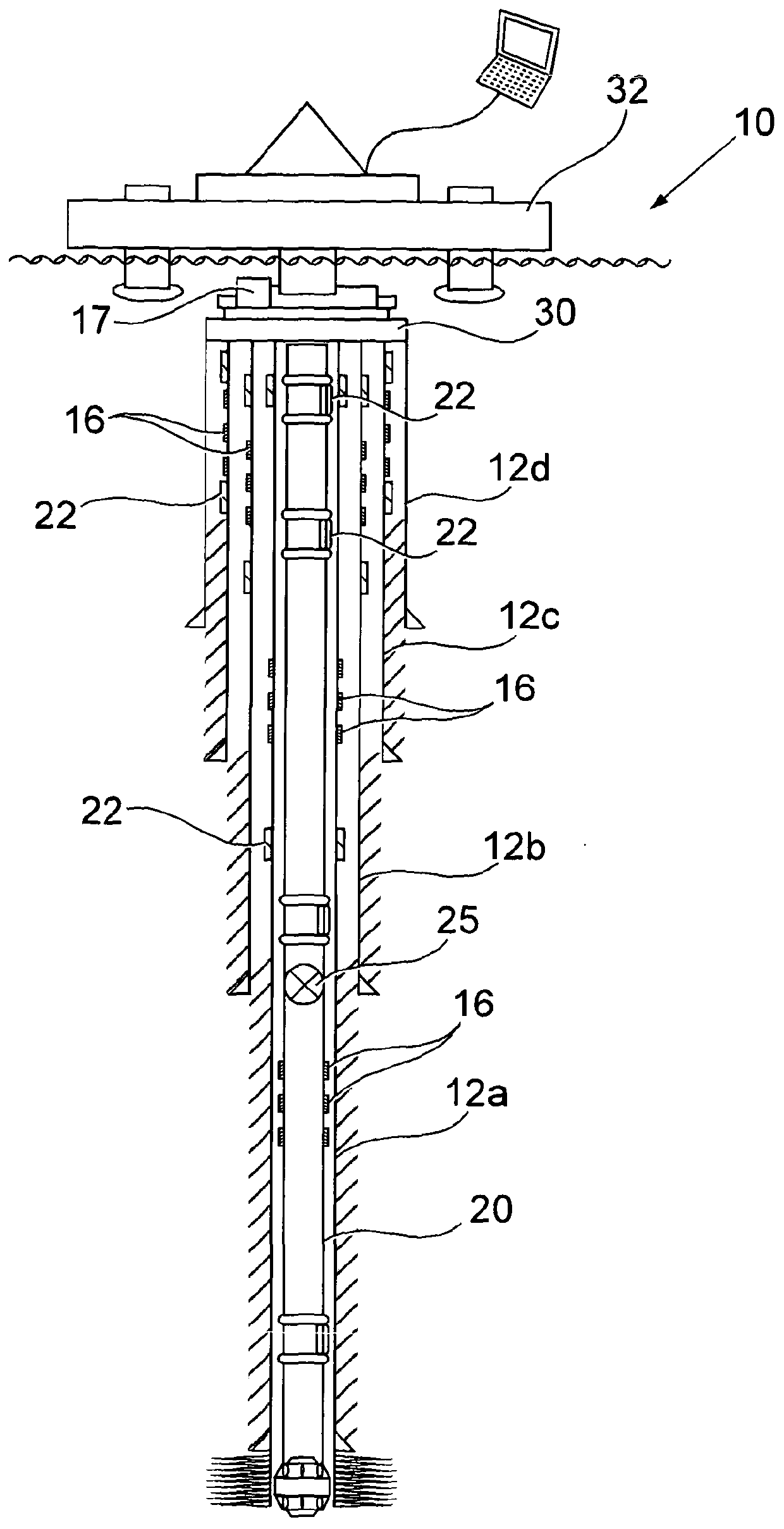
[0087] figure 1 A well 10 is shown comprising a series of casing strings 12a, 12b, 12c and 12d and adjacent annulus A, B between each string of casing and tubing strings within each string of casing. , C, D, the drill string 20 is disposed inside the innermost casing 12a.

[0088] As is common in the prior art, each casing string extends further into the well than the adjacent casing string outside it. Also, the lowest portion of each casing string is bonded in place due to the casing string extending below its outer adjacent string.

[0089] According to the invention, sensors 16 are provided on the casing above the bonded portion and on the drill string 20 . Additionally, other sensors (not shown) are positioned at various points within the cased and / or uncased borehole of the well. The sensors include transmitters to send data to a communication box 17 on the BOP 30 . In an alternative embodiment, a communications box or "black box" including a sonar transceiver and aco...


PUM


Abstract

A well comprising a borehole and a wellhead, and a communication box at or proximate to the wellhead, the well including a plurality of sensors coupled to a wireless transmitter adapted to sending information from the sensor to the communication box; the sensor includes at least one pressure sensor; and the well includes a first storage device spaced from the communication box, the first storage device configured to storing information from said sensor; wherein said communication box comprises: a receiver adapted to receive a signal from said transmitter, and a transmitter adapted to transmit and / or store data received from said transmitter at least one of the storage device and the second storage device. The communication box is usually highly shock resistant (withstands about 50Gs of vibration in all axes for at least 5ms) and, along with other optional features, provides a system for monitoring the well especially before, during or after an emergency .

Description

technical field [0001] The present invention relates to an improved and improved system for determining conditions in wells, especially during or after emergency situations. Background technique [0002] The drilling of boreholes for oil and gas wells is a complex and expensive task in which reservoir characteristics are exploited such that the wells are designed and positioned to recover the hydrocarbons as efficiently as possible. [0003] A borehole is first drilled to a certain depth, and a string of casing is inserted into the borehole. The annulus between the casing and the borehole is then usually cemented in order to secure and seal the casing. The borehole is typically extended to further depths by continuing drilling below the cased borehole at a smaller diameter than the borehole was first drilled at, and the deeper borehole is then cased and cemented. The result is a borehole with a number of generally coaxial tubular columns / casing strings that progressively d...

Claims


Application Information

Patent Timeline
Patent Type & Authority Patents(China)
IPC IPC(8): E21B47/12E21B47/13E21B47/14E21B47/001
CPCE21B47/14E21B47/13E21B47/12E21B47/001
Inventor 肖·康普顿·罗斯莱斯利·大卫·贾维斯
Owner METROL TECH
Learn More