Computer auxiliary centering installation and correction device and method for diffraction element

A computer-aided, diffractive element technology, used in auxiliary devices, tool holder accessories, turning equipment, etc., can solve problems such as large errors, inability to generate spherical center images with diffractive elements, and low efficiency, and achieve the effect of solving low efficiency.

Active Publication Date: 2015-04-22
INST OF OPTICS & ELECTRONICS - CHINESE ACAD OF SCI
View PDF5 Cites 0 Cited by
  • Summary
  • Abstract
  • Description
  • Claims
  • Application Information

AI Technical Summary

Problems solved by technology

[0004] The purpose of the present invention is to solve the problem that traditional optical elements need to be subjectively judged by the human eye to be used for the spherical center image of the center, but the diffraction element cannot produce the spherical center image; the traditional optical element alignment needs to manually adjust the lens displacement, The technical problem of large errors and low efficiency, in order to solve the above problems, the present invention provides a method and device for computer-aided alignment of diffraction elements in a refraction-diffraction hybrid imaging system

Method used


Image

  • Computer auxiliary centering installation and correction device and method for diffraction element
  • Computer auxiliary centering installation and correction device and method for diffraction element
  • Computer auxiliary centering installation and correction device and method for diffraction element

Examples


Embodiment Construction

[0060] In order to make the purpose, technical solution and advantages of the device of the present invention clearer, the present invention will be further described in detail below in conjunction with the accompanying drawings.

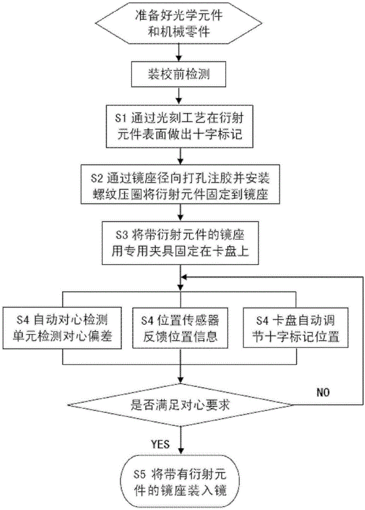
[0061]In the method and device of the invention, a computer is used to control the centering of the diffraction element, which improves the accuracy and efficiency of the centering alignment of the diffraction element, and realizes the automatic closed-loop feedback control of the centering alignment of the diffraction element.

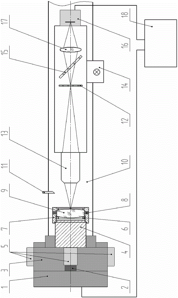
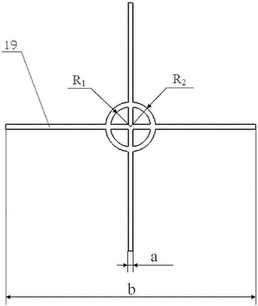
[0062] Improve and innovate the traditional optical lens lathe alignment method. A special cross mark for centering is processed in the center of the diffraction element by photolithography technology. The centering and calibrating device self-assembled by high-precision lathe, self-made centering detection system, electric inner ball head four-jaw chuck, driver, position sensor and computer is used as the main centering an...


PUM


Abstract

The invention provides a computer auxiliary centering installation and correction device and a method for a diffraction element. The computer auxiliary centering installation and correction device for the diffraction element comprises a lathe main shaft, a location sensor, a chuck, a special fixture, an actuator, a threaded pressing ring, a microscope base, silica gel, lathe guide rail, a lather tool, a differentiation plate, an overlength working distance microscope objective, a light source, a half-reaction semi-permeable mirror, a charge coupled device (CCD) camera, a CCD imaging lens, a computer and a cross label. A special cross label is manufactured at the center of the diffraction element, a centering detection unit detects centering deviation, and meanwhile the computer automatically adjusts the location of the chuck according to location data which are fed back by the location sensor until the center precision meets a requirement of a tolerance, so automatic adjustment of the chuck stops. Finally, the microscope base which is provided with the diffraction element is conducted centering turning and is installed into a lens barrel. The computer auxiliary centering installing and correcting device and the method for the diffraction element solve the problems that centering center of sphere image can not be produced when the diffraction element is conducted centering installation and correction and manual adjustment of the chuck is low in efficiency and precision and achieves the computer auxiliary control on the diffraction element centering installation and correction.

Description

technical field [0001] The invention belongs to the technical field of high-precision optical-mechanical system installation and calibration, and relates to the improvement and innovation of a computer-aided calibration method and device for a diffraction element in a refraction-diffraction hybrid imaging system. Background technique [0002] In the refraction-diffraction hybrid imaging system, the use of diffraction elements to replace traditional optical elements can significantly reduce the number of optical elements used, making the system simple in structure, small in size and light in weight. Utilizing the flexible wavefront modulation capability, high degree of design freedom and phase transformation characteristics of the diffraction element, the refraction-diffraction hybrid imaging system can effectively correct aberrations such as chromatic aberration, spherical aberration, and astigmatism, and obtain better image quality than traditional optical systems. The emer...

Claims


Application Information

Patent Timeline
Patent Type & Authority Patents(China)
IPC IPC(8): B23B25/06
Inventor 罗先刚王彦钦杨欢张鸶懿
Owner INST OF OPTICS & ELECTRONICS - CHINESE ACAD OF SCI
Why Eureka
Try Eureka