
Wiper arm linkage system

A wiper and connected technology, applied in sliding contact bearings, vehicle maintenance, bearings, etc., can solve problems such as complex transportation and rising product costs, achieve economies of scale, and simplify supply chain logistics.

Active Publication Date: 2016-06-22
VALEO SYST DESSUYAGE
View PDF5 Cites 0 Cited by
  • Summary
  • Abstract
  • Description
  • Claims
  • Application Information

AI Technical Summary

Problems solved by technology

Having different types of housings complicates the shipping required for the supply chain, ultimately driving up the cost of the product

Method used


Image

  • Wiper arm linkage system
  • Wiper arm linkage system
  • Wiper arm linkage system

Examples


Embodiment Construction

[0029] The present invention relates to a coupling system, and more particularly to a coupling system for transmitting power from an electric motor to a wiper mechanism of a wiper device in a motor vehicle wiper system.

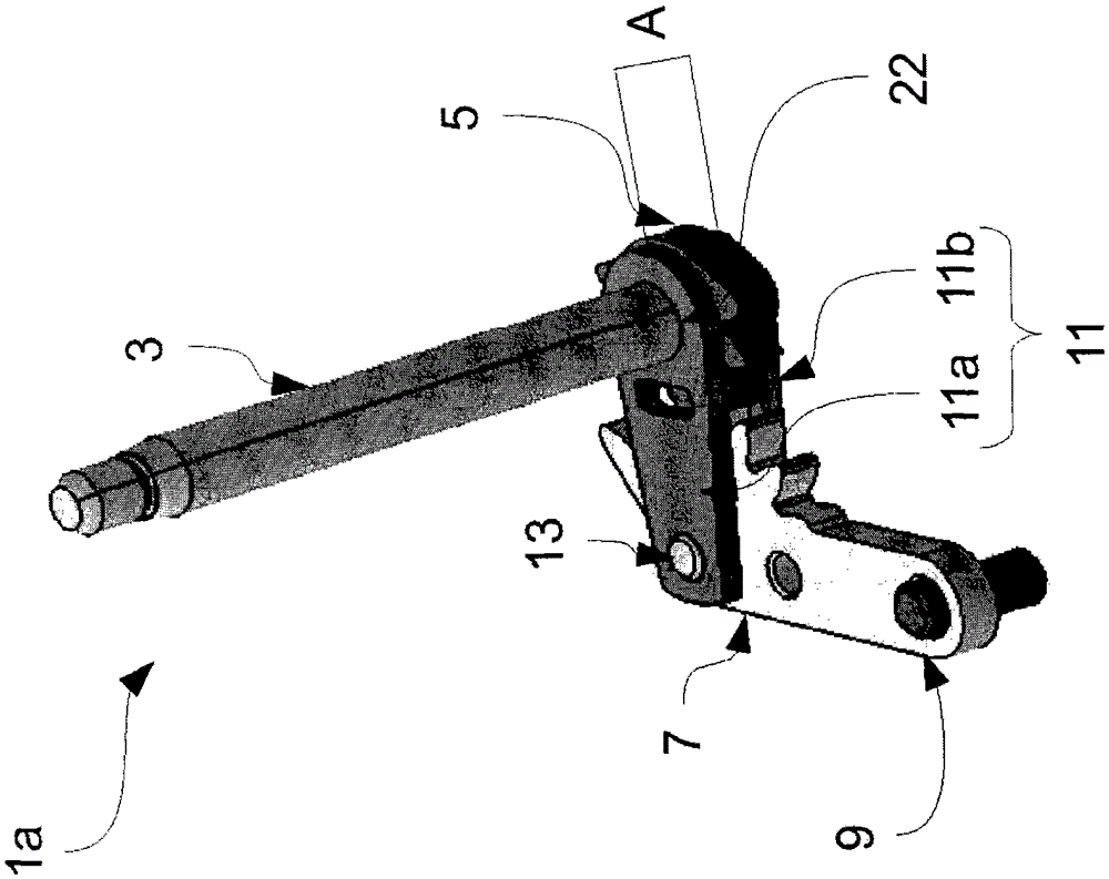
[0030] figure 1 A geared coupling system 1a is shown. Said coupling system comprises in particular a shaft 3 which is rotated by an electric motor (not shown), possibly via a transmission mechanism. The shaft 3 is fixedly attached to a first toothed wheel 5 which itself meshes with a toothed part of a second toothed wheel 7 (which forms the base of the arm 9 ), said The arm 9 is itself connected to a wiper mechanism of a wiper device (not shown).

[0031] The toothed wheels 5, 7 are held at intermeshing distance by the half-cranks 11a, 11b, which are two elongated metal plates perforated at their ends respectively to allow shaft 3 and the pivot 13 to which the second toothed wheel 7 forming the base of the arm 9 is hinged. Said pivot 13 comprises a cylind...


PUM


Abstract

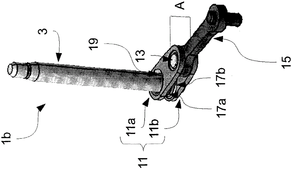
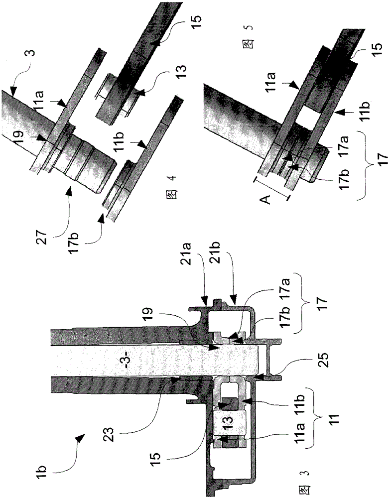
The invention relates to a wiper arm coupling system (1b) for converting a rotational movement of a shaft (3) into a translational movement of a connecting rod (15), said coupling system (1b) comprising a coupling system accommodating gear meshes ( 1a) the housing (21), the crank (11) formed by two half-cranks (11a, 11b) engaged with the shaft (3), the pivot (13) at the end of said crank (11), Link (15) articulated to said pivot (13), characterized in that said crank (11) comprises a spacer (17) located between said half-cranks (11a, 11b) when abutting against Spacers (17) are placed with half-cranks (11a, 11b) spaced at least around said shaft (3) in accordance with the thickness (A) of the gear mesh coupling system (1a), so that said housing (21) At least around the shaft (3) is formed a sliding bearing bringing the two half-cranks (11a, 11b) into sliding contact.

Description

technical field [0001] The invention relates to a coupling system, in particular for a vehicle windshield wiper. Background technique [0002] Motor vehicle wiper motors generate a rotational motion which needs to be converted into a wiping motion of the wiper blade. [0003] For this conversion, it is known in practice to use a linkage mechanism, which converts the rotational movement of the output shaft of the motor into a translational movement of the connecting rod, which in turn moves the wiper blade. [0004] Said linkages, also referred to as linkage systems, are usually housed in a housing formed by a cover and a base, in order to protect it from the external environment. [0005] There are two well-known different types of linkage systems, geared and non-geared. [0006] For example the gear meshing mechanism described in the patent DE3247421. In these mechanisms, the shaft moves an at least partially toothed wheel in mesh with a complementary toothed portion of ...

Claims


Application Information

Patent Timeline
Patent Type & Authority Patents(China)
IPC IPC(8): B60S1/18
CPCB60S1/166B60S1/24F16C17/02F16C2326/09B60S1/18
Inventor P·布兰切特A·瑟维恩L·尼考德Y·雷奎拉德
Owner VALEO SYST DESSUYAGE
Learn More