Water intake structure for water intake well
A technology for water intakes and water intake wells, applied in water supply devices, drinking water devices, buildings, etc., can solve problems such as filter clogging, clogging, deterioration of filter water collection efficiency, etc., and achieve the effect of preventing loss and deformation
- Summary
- Abstract
- Description
- Claims
- Application Information
AI Technical Summary
Problems solved by technology
Method used
Image

Examples
Embodiment Construction
[0029] Embodiments of the present invention will be described below with reference to the drawings.
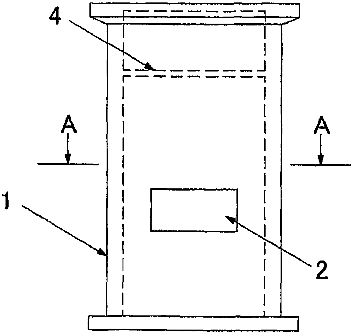
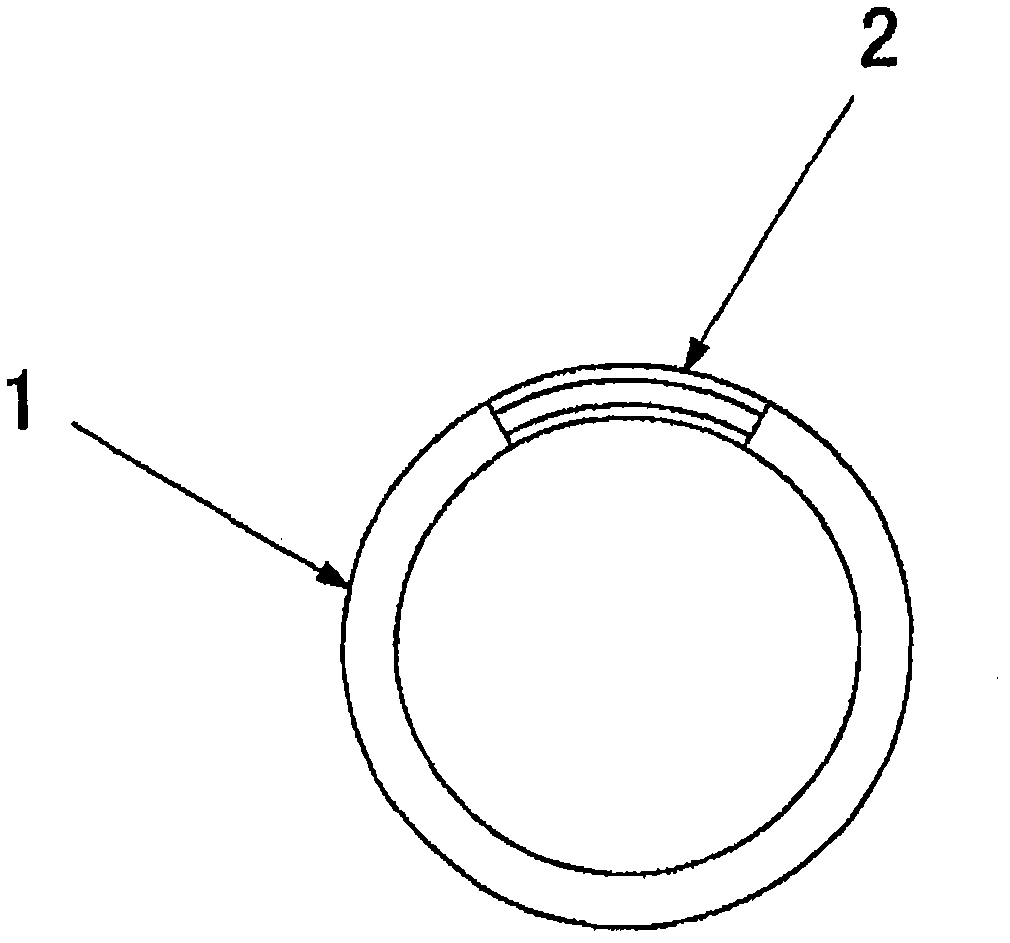
[0030] exist figure 1 and figure 2 Among them, a water intake well 1 with an elliptical cross section is formed into a cylindrical shape with an elliptical cross section by materials such as concrete or steel, and a substantially rectangular water intake 2 in a front view is provided at the lower part thereof. Mark 4 is an intermediate gangway for workers to use during construction. In this embodiment, the water intake is formed at a predetermined height on a part of the peripheral surface of the water intake well, but may be formed over the entire circumference of the water intake well. The diameter of the water intake well 1 is usually 2 m to 10 m, but it is not limited thereto.
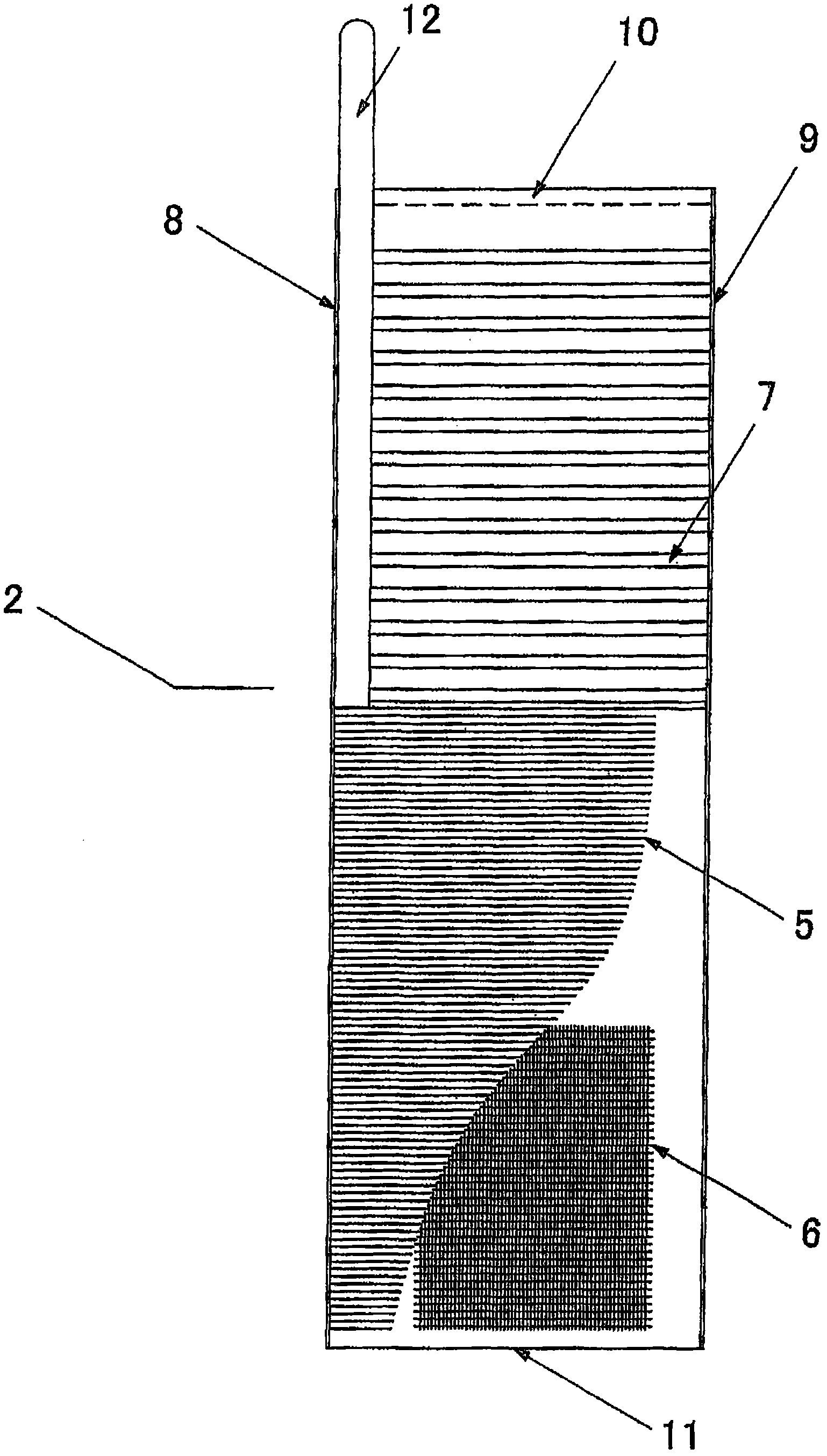
[0031] Such as image 3 As shown, viewed from the outside of the water intake well to the inside, the water intake 2 is equipped with a filter protection pipe 5, a filter 6, and a backwash pip...
PUM
 Abstract
Description
Claims
Application Information