In-situ test method for buried pipeline across faults

A technology for in-situ testing and buried pipelines, which is applied in the field of cross-fault buried pipeline tests and test devices for testing reverse fault action in in-situ tests of cross-fault buried pipelines, and can solve problems such as ignoring the effects of pipeline joint connections Achieve the effects of convenient loading method and reliable and effective analysis results

Inactive Publication Date: 2015-10-14
NANJING TECH UNIV
View PDF5 Cites 0 Cited by
  • Summary
  • Abstract
  • Description
  • Claims
  • Application Information

AI Technical Summary

Problems solved by technology

The current model test methods for buried pipelines have the following main problems: ①The methods mostly use soil box loading, which equivalently simplifies the boundary constraints of the pipeline; ②The methods mostly use non-joint pipes as the research object, ignoring the effect of the actual pipeline joint connection; ③The test pipes are mostly in the no-load working state; ④Due to the equivalent scaling of the model in the model test method, there is an inevitable actual size effect
Existing test methods face many problems, but the key issue is how to make the test model more consistent with the actual situation of earthquake damage, and in this case, to study the mechanical performance and failure mechanism of buried pipelines across reverse faults

Method used


Image

  • In-situ test method for buried pipeline across faults
  • In-situ test method for buried pipeline across faults
  • In-situ test method for buried pipeline across faults

Examples


Embodiment Construction

[0034] The present invention will be further described below in conjunction with the accompanying drawings and embodiments.

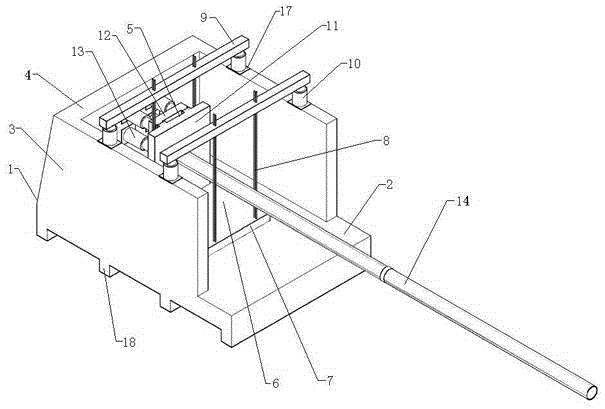
[0035] Such as Figure 1-7 Shown: an in-situ test method for buried pipelines across faults, the steps used in the test method are as follows:

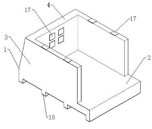
[0036]A. Select the test site and pour the reaction force device 1, wherein the reaction force device 1 includes the integrated reaction force platform 2, the vertical reaction force wall 3, the horizontal reaction force wall 4 and the foundation beam 19, wherein the vertical reaction force Wall 3 and horizontal reaction force wall 4 also can adopt vertical reaction force frame and horizontal reaction force frame, two vertical reaction force walls 3 are respectively positioned at the both sides of horizontal reaction force wall 4 and vertical reaction force wall 3 and horizontal reaction force wall The force wall 4 is arranged vertically on the upper surface of the counter force pedestal 2 in a "匚" shape, and ...


PUM


Abstract

The invention discloses a method of fault-striding buried pipeline in-situ test. The method comprises the following steps: selecting a test field, pouring a counter-force device (1), and arranging a horizontal moving device (5), a vertical moving device (6) and a displacement meter; arranging a test device on a test pipeline (14); connecting a data collecting device with a data collecting system; processing the test pipeline (14), placing the test pipeline (14) into an excavated ditch, and fixing the test pipeline (14) on the horizontal moving device (5); tamping backfilled soil in layers and measuring a displacing pointer, the planer coordinates and vertical elevation of a small wood pile; preloading and debugging the devices; and formally loading collected test data, and finally obtaining a test result after managing and analyzing the data. The invention provides a novel original-position original-type original-shape reverse fault dislocation quantity applying method. The method gives consideration to influence of factors such as connectors of the test pipeline and a load state, conforms to the actual stress state of the buried pipeline, and is more reliable and effective in analysis result.

Description

technical field [0001] The invention relates to the technical field of disaster prevention and mitigation of lifeline engineering, in particular to a test device for checking the action of a reverse fault in an in-situ test of a buried pipeline crossing a fault, in particular to a test method for a buried pipeline crossing a fault. Background technique [0002] Buried pipelines occupy an important position in modern production and life, and are important lifeline projects. The destruction of buried pipelines will not only cause huge economic losses, but also cause serious secondary disasters, which will have a major impact on post-earthquake disaster relief, production, life and the restoration of social order. The buried pipeline system is a typical line and network project, which inevitably needs to cross some unfavorable or dangerous areas for earthquake resistance. Crossing faults is one of the key engineering problems that buried pipelines have to face and need to solve...

Claims


Application Information

Patent Timeline
Patent Type & Authority Patents(China)
IPC IPC(8): G01M99/00
Inventor 李鸿晶薛娜刘爱文周正华赵雷李秀菊
Owner NANJING TECH UNIV
Why Eureka
Try Eureka