Current mutual inductor residual magnetism detection method based on small-signal gradient mapping

A technology of a current transformer and a detection method, which is applied in the field of current transformer remanence detection based on small signal slope mapping, can solve the problem of inability to measure the size of the current transformer's remanence, and achieve the effect of accurate remanence.

Active Publication Date: 2013-05-15
STATE GRID JIANGSU ELECTRIC POWER CO ELECTRIC POWER RES INST +2
View PDF7 Cites 19 Cited by
  • Summary
  • Abstract
  • Description
  • Claims
  • Application Information

AI Technical Summary

Problems solved by technology

These methods cannot measure the magnitude of the residual magnetism of the current transformer under any residual magnetization state

Method used


Image

  • Current mutual inductor residual magnetism detection method based on small-signal gradient mapping
  • Current mutual inductor residual magnetism detection method based on small-signal gradient mapping
  • Current mutual inductor residual magnetism detection method based on small-signal gradient mapping

Examples


Embodiment Construction

[0018] The present invention will be further described below in conjunction with the accompanying drawings.

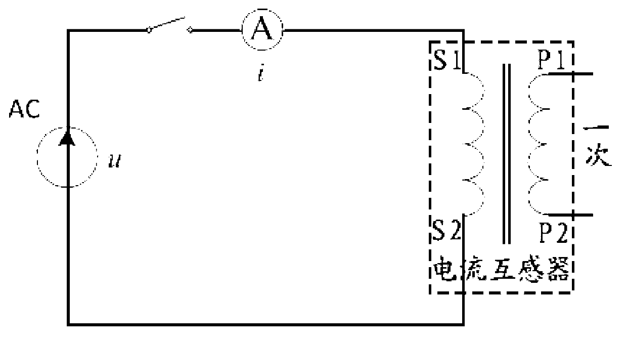
[0019] Firstly, the principle description of the current transformer residual magnetism detection method based on the small signal slope mapping is given, as shown in figure 1 As shown, the current transformer (referred to as CT) is open circuit at the first time, and the second time is connected to the AC power circuit, and a small AC voltage u is applied to the CT to measure the circuit current i.

[0020] Assuming that at time t=0, CT is open circuit once, and the voltage added for the second time is u=U m sinωt (ω=50Hz), ignoring the CT secondary side resistance, the CT secondary voltage balance equation is:

[0021] u = dφ dt = dφ di · di dt - - - ( 1 ...


PUM


Abstract

The invention discloses a current mutual inductor residual magnetism detection method based on small-signal gradient mapping. A differential coefficient of an initial operating point magnetic flow with respect to an exciting current is computed by exerting small voltage signals on a current mutual inductor for a second time, magnetizing curves of an iron core of the current mutual inductor are used for gradient mapping so as to confirm residual magnetism of the iron core of the current mutual inductor. According to the current mutual inductor residual magnetism detection method based on small-signal gradient mapping, the practical current mutual inductor is magnetized, so that current mutual inductance produces residual magnetism of different quantities. Effectiveness of the residual magnetism detection method and theory and practicability of a detection system platform are assessed, and the detection result indicates that the detection system platform is capable of quickly and accurately reflecting the quantity of residual magnetism of the iron core of the detected current mutual inductor.

Description

technical field [0001] The invention relates to a method for detecting residual magnetism of an iron core of a current transformer, in particular to a method for detecting residual magnetism of a current transformer based on small-signal slope mapping, which belongs to the electric power automation technology. Background technique [0002] When the line of the power system is in line with operation, short-circuit fault or harmonic is serious, there will be a considerable DC component in the transient process of the line current, which will cause residual magnetism in the iron core. Current transformers (CT) in operation generally have residual magnetism, which is harmful to current transformers, and once generated, residual magnetism will not disappear automatically, and will exist for a long time under normal operating conditions, so Affect the spread characteristics and accuracy of the current transformer. [0003] For current transformers that are already in operation an...

Claims


Application Information

Patent Timeline
Patent Type & Authority Applications(China)
IPC IPC(8): G01R33/12
CPCG01R33/123
Inventor 袁宇波李鹏黄浩声张佳敏王忠东
Owner STATE GRID JIANGSU ELECTRIC POWER CO ELECTRIC POWER RES INST
Why Eureka
Try Eureka