Power clamping electrostatic discharge protection circuit

An electrostatic discharge protection and electrostatic discharge technology, applied in the field of power supply clamp electrostatic discharge protection circuits, can solve problems such as false triggering of clamp transistor 1

Active Publication Date: 2013-05-15
PEKING UNIV
View PDF4 Cites 22 Cited by
  • Summary
  • Abstract
  • Description
  • Claims
  • Application Information

AI Technical Summary

Problems solved by technology

[0007] like figure 1 The problem of the prior art shown is that the capacitor C1 and the resistor R1 undertake the tasks of judging and delaying at the same time
In order to obtain a sufficient ESD turn-on delay (for example, 500ns), there must be a large enough capacitor C1 and resistor R1. However, when the power supply is powered on quickly (for example, 100ns rise time), the charging of capacitor C1 through resistor R1 is will not be able to keep up with the change, at this time, it will cause false triggering of the clamping transistor 1

Method used


Image

  • Power clamping electrostatic discharge protection circuit
  • Power clamping electrostatic discharge protection circuit
  • Power clamping electrostatic discharge protection circuit

Examples


Embodiment Construction

[0042] A power supply clamp electrostatic discharge protection circuit proposed by the present invention will be described in detail below with reference to the drawings and embodiments.

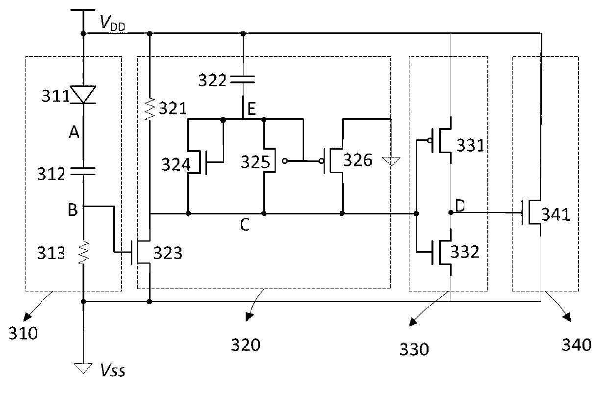
[0043] Such as figure 2 and image 3 As shown, the present invention provides a power supply clamp electrostatic discharge protection circuit, including a power supply pin VDD, a ground pin VSS, a determination circuit 310, a delay circuit 320, a trigger circuit 330 and a clamp circuit 340; wherein:

[0044] The power supply pin VDD is used to connect to a power supply to provide a power supply voltage;

[0045] The ground pin VSS is used to provide low level;

[0046] A determination circuit 310, which is connected between the power supply pin VDD and the ground pin VSS, and is used to sense the voltage of electrostatic discharge;

[0047] Delay circuit 320, its input end is connected with the output end of described judging circuit 310, is used for recording and retaining the electrost...


PUM


Abstract

The invention provides a power clamping electrostatic discharge protection circuit which comprises a power pin, a grounding pin, a decision circuit (310), a time-delay circuit (320), a trigger circuit (330) and a clamping circuit (340), wherein the decision circuit (310) is used for sensing of an electrostatic discharge voltage, the time-delay circuit (320) is used for recording and storing a sensed electrostatic discharge voltage signal so as to provide time delay, the trigger circuit (330) is used for converting the electrostatic discharge voltage signal stored by the time-delay circuit (320) to an electrostatic discharge trigger signal, and the clamping circuit (340) is used for bleeding electrostatic current after the electrostatic discharge trigger signal is received. The decision circuit and the time-delay circuit are separated, the probability of clamping circuit false triggering caused by rapid electrifying is avoided, and meanwhile, a longer starting time for the clamping circuit can be obtained when electrostatic discharge impact occurs, and the reliability of electrostatic discharge protection is improved.

Description

technical field [0001] The invention relates to the technical field of electronic static discharge (ESD) protection of integrated circuit chips, in particular to a power clamp ESD protection circuit in which a determination unit and a delay unit are separated. Background technique [0002] With the continuous shrinking of the feature size of the integrated circuit process, the anti-static discharge capability of the chip has become a key factor to ensure the reliable operation of the internal circuit. The electrostatic discharge phenomenon refers to the transient process of electrostatic charge transfer between two objects with unequal potentials approaching or touching. At the advanced level of integrated circuit technology, the gate oxide layer of the device is very thin, and its equivalent gate oxide layer capacitance is very small. When electrostatic charges accumulate on the gate oxide layer, a large equivalent gate voltage will be formed, resulting in failure of a dev...

Claims


Application Information

Patent Timeline
Patent Type & Authority Applications(China)
IPC IPC(8): H02H9/04
Inventor 王源刘琦陆光易曹健贾嵩张兴
Owner PEKING UNIV
Why Eureka
Try Eureka