
Piezoelectric actuator outputting dynamic micro angular displacement

A piezoelectric actuator, micro-angle technology, applied in piezoelectric effect/electrostrictive or magnetostrictive motors, electrical components, generators/motors, etc., can solve the problem of limiting the use of piezoelectric stack actuators, etc. problem, to achieve the effect of light weight, compact structure and no clearance

Active Publication Date: 2014-07-02
XI AN JIAOTONG UNIV
View PDF2 Cites 0 Cited by
  • Summary
  • Abstract
  • Description
  • Claims
  • Application Information

AI Technical Summary

Problems solved by technology

However, most of the piezoelectric actuators currently used are actuators that can only output linear displacement.
In the case where the output of micro-rotation angle is required, the simple use of linear actuators has certain limitations, which limits the use of piezoelectric pile actuators

Method used


Image

  • Piezoelectric actuator outputting dynamic micro angular displacement
  • Piezoelectric actuator outputting dynamic micro angular displacement

Examples


Embodiment Construction

[0015] The present invention will be described in further detail below in conjunction with the accompanying drawings and specific embodiments.

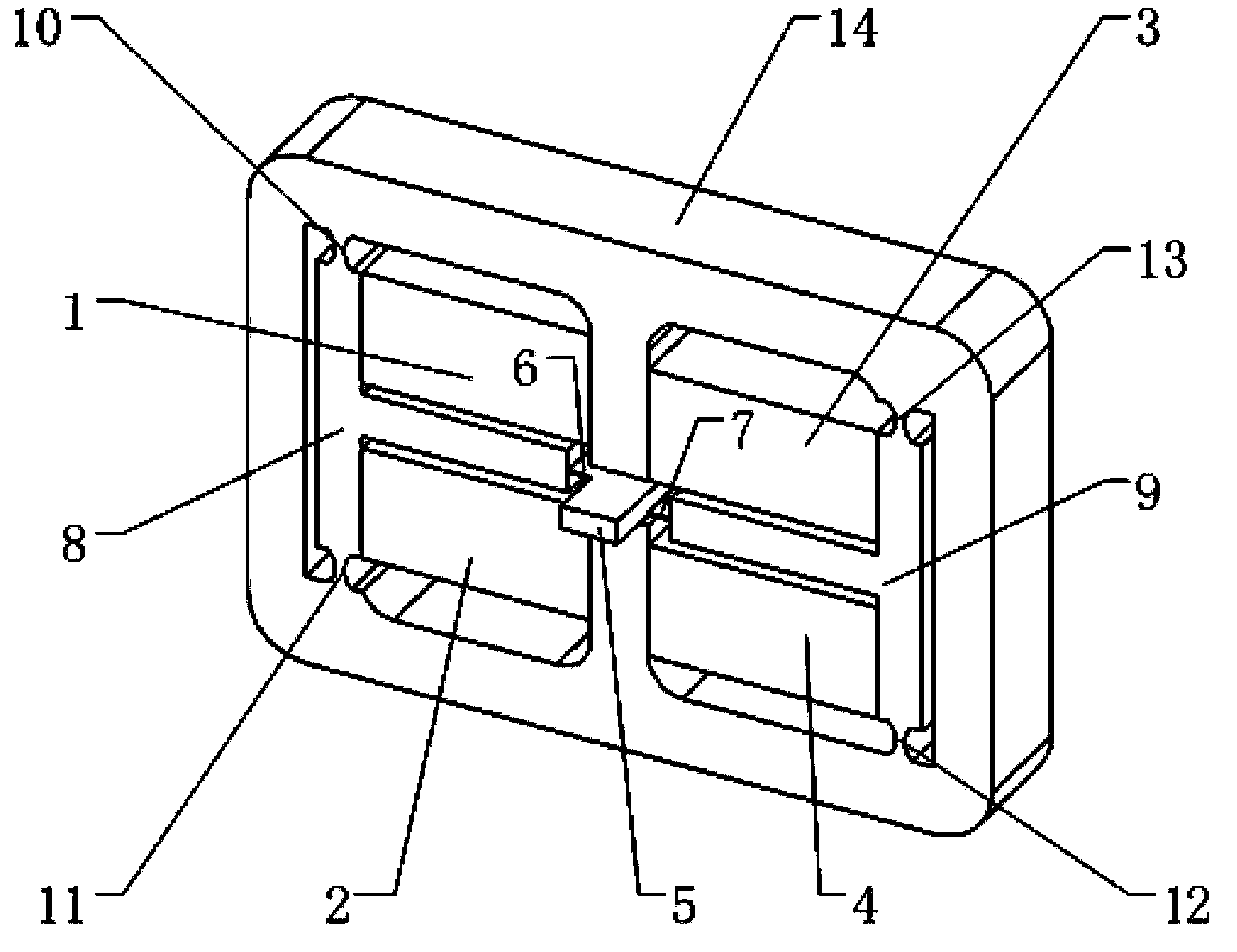
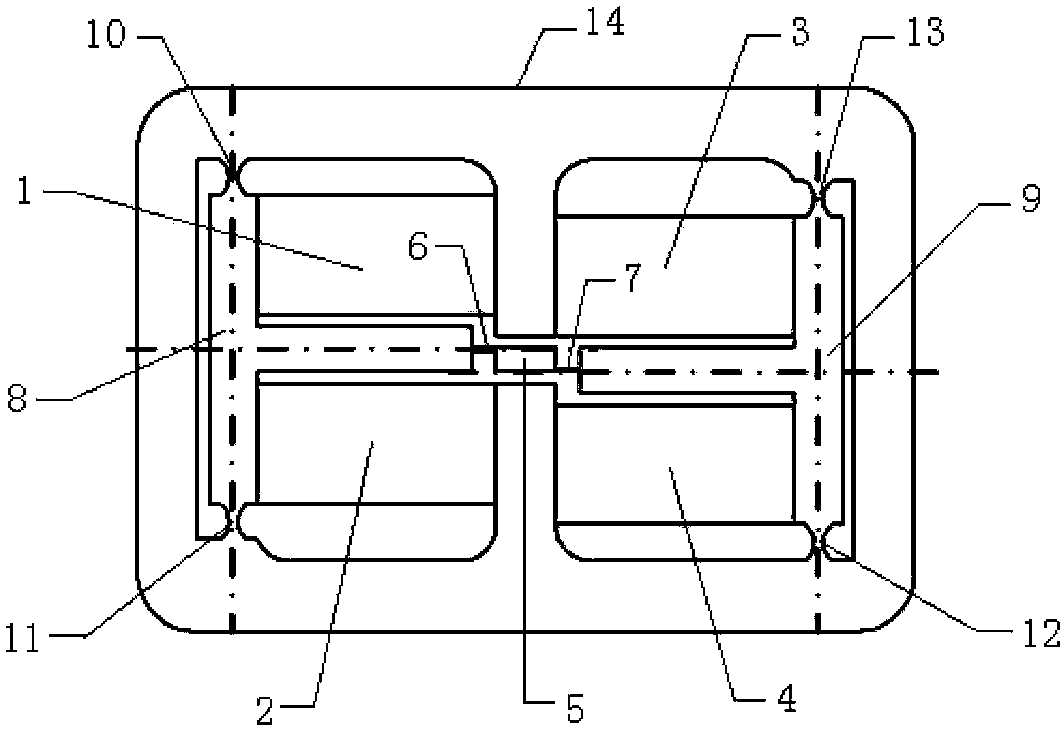
[0016] Such as figure 1 As shown, a piezoelectric actuator for outputting dynamic micro-angular displacement of the present invention includes an output rod 5, a first reed 6 and a second reed 7 respectively connected to the upper and lower ends of the output rod 5, and the first reed Sheet 6 is connected with the first T-shaped flexible constraint end 8, and the second T-shaped flexible constraint end 9 connected with the second reed 7, and the first T-shaped flexible constraint end 8 passes through the first flexible hinge 10 and the second flexible hinge 10 on both sides of the first T-shaped flexible constraint end. The flexible hinge 11 is connected in the external fixed frame 14, the second T-shaped flexible constraint end 9 is connected in the external fixed frame 14 by the third flexible hinge 12 and the fourth flexible hinge ...


PUM


Abstract

The invention relates to a piezoelectric actuator outputting dynamic micro angular displacement which comprises an output rod, a first spring slice and a second spring slice, a first T-shaped flexible restraint end connected with the first spring slice and a second T-shaped flexible restraint end connected with the second spring slice. The first spring slice and the second spring slice are respectively connected with upper and lower ends of two sides of the output rod. The first T-shaped flexible restraint end is connected in an external fixed frame through a first flexible hinge and a second flexible hinge on two sides of the first T-shaped flexible restraint end. The second T-shaped flexible restraint end is connected in an external fixed frame through a third flexible hinge and a fourth flexible hinge on two sides of the second T-shaped flexible restraint end. A first piezoelectric stack and a second piezoelectric stack are fixed on the first T-shaped flexible restraint end and the outer fixed frame. A third piezoelectric stack and a fourth piezoelectric stack are fixed on the second T-shaped flexible restraint end and the outer fixed frame. After forward voltage is exerted, length of the four piezoelectric stacks is prolonged and the two T-shaped flexible restraint ends are pushed to move to two sides so as to pull the two spring slices to two sides and consequentially, the output rod rotates around the symmetric center and micro angular displacement is output. The piezoelectric actuator is compact in structure, little in size and light in weight.

Description

technical field [0001] The invention relates to a piezoelectric actuator, in particular to a piezoelectric actuator outputting dynamic micro-angular displacement. Background technique [0002] Actuators based on piezoelectric materials have been widely used in microelectronics technology, bioengineering, aerospace engineering and other fields. It has the characteristics of compact structure and high control precision. However, most of the piezoelectric actuators currently used are actuators that can only output linear displacement. In the case where the output of micro-rotation angle is required, there are certain limitations in the simple use of linear actuators, which limits the use of piezoelectric pile actuators. Contents of the invention [0003] The purpose of the present invention is to overcome the deficiencies of the prior art and provide a piezoelectric actuator that outputs dynamic micro-angular displacements. The actuator has a compact structure, small volume...

Claims


Application Information

Patent Timeline
Patent Type & Authority Patents(China)
IPC IPC(8): H02N2/02
Inventor 敬子建徐明龙杨克亚李亮
Owner XI AN JIAOTONG UNIV
Learn More