Line filter, AC power supply and method for manufacturing the line filter

A technology of AC power supply and AC power, applied in AC network to reduce harmonics/ripples, conversion equipment with intermediate conversion to AC, electrical components, etc., can solve the problem of increased manufacturing costs, increased drilling work, and linear filters Larger area and other issues, to achieve the effect of process reduction, PCB area reduction and cost saving

Active Publication Date: 2013-05-15
LG INNOTEK CO LTD
5 Cites 0 Cited by

AI-Extracted Technical Summary

Problems solved by technology

[0010] However, in figure 2 In the case of the two-stage linear filter shown, since the two linear filters are provided consecutively on the PCB, the area of ​​the linear filter becomes larger than tha...

Method used

[0059] Meanwhile, the integral two-stage linear filter according to one embodiment may include a case that supports the linear filter and is used for mounting on an inverted substrate. The case covers the sides of the bobbin 100 , thereby preventing the bobbin 100 from shaking while preventing interference of separate peripheral parts or wires disposed adjacent to the coils 120 and 130 due to external shock of the electric appliance.
[0061] In this case, the connector may include four connectors for connecting the live wire 141 and the neutral wire 142 of the input wire 140 and the live wire 151 and the neutral wire 152 of the output wire 150, and may be sequentially arranged in the ...

Abstract

The invention discloses a line filter, an AC power supply, and a method for manufacturing the line filter. The line filter outputs the AC power supply via removing noise from the AC power supply. The line filter comprises a winding barrel, a first coil, a second coil, and a connecting line. The winding barrel is provided with two surfaces, coils are winded at the two surfaces, the first coil winds around a first surface of the winding barrel and is connected to an input line, the second coil winds around a second surface of the winding barrel and is connected to an output line, the connecting lines connect the first coil to the second coil and filtering of the AC power supply provided by the first coil is performed to transmit the AC power supply to the second coil.

Application Domain

Multiple-port networksApparatus with intermediate ac conversion +2

Technology Topic

AC powerLine filter +2

Image

  • Line filter, AC power supply and method for manufacturing the line filter
  • Line filter, AC power supply and method for manufacturing the line filter
  • Line filter, AC power supply and method for manufacturing the line filter

Examples

  • Experimental program(1)

Example Embodiment

[0041] Hereinafter, the present disclosure will be described in more detail with reference to the accompanying drawings.
[0042] In the following description, in order to facilitate the description of the specification, only the suffixes "module" and "unit" are added, and the suffixes "module" and "unit" can be used compatible with each other.
[0043] In addition, although the embodiments will be described in detail below with reference to the drawings and the contents marked in the drawings, the embodiments are not limited thereto.
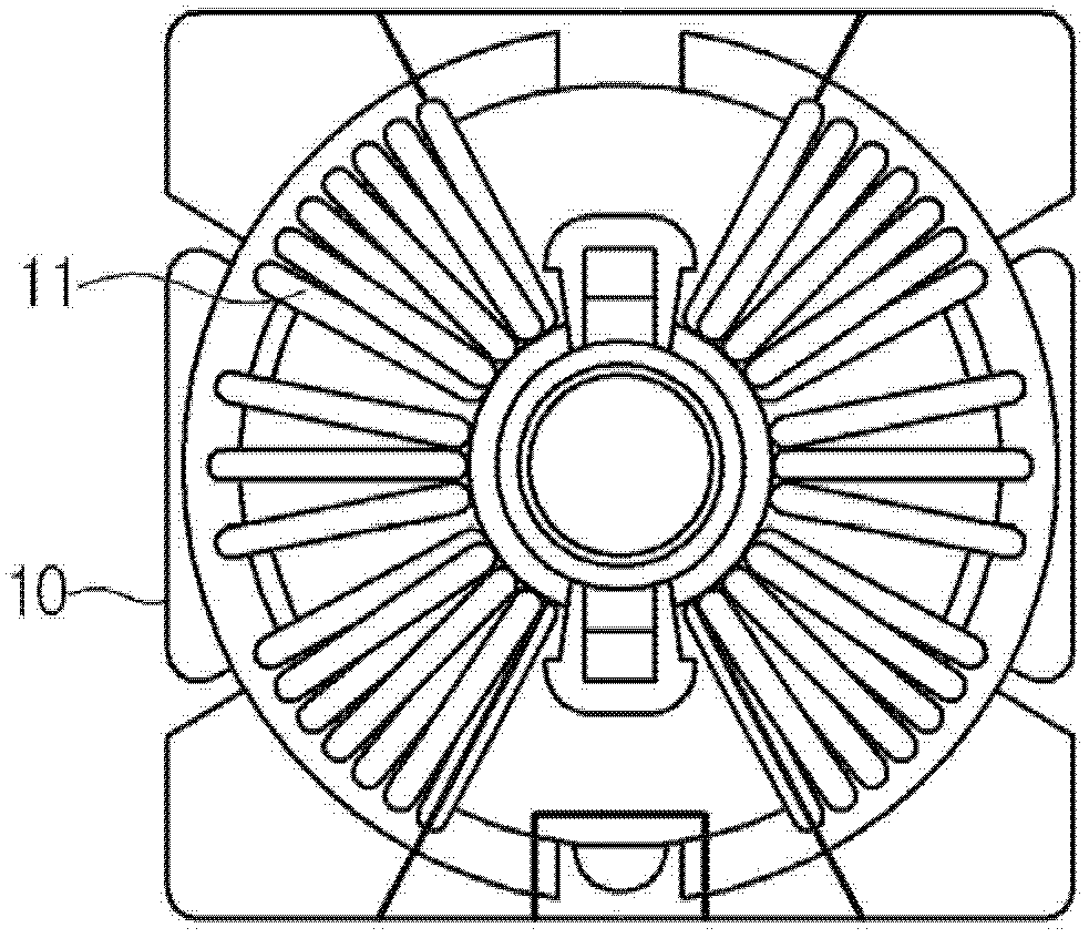
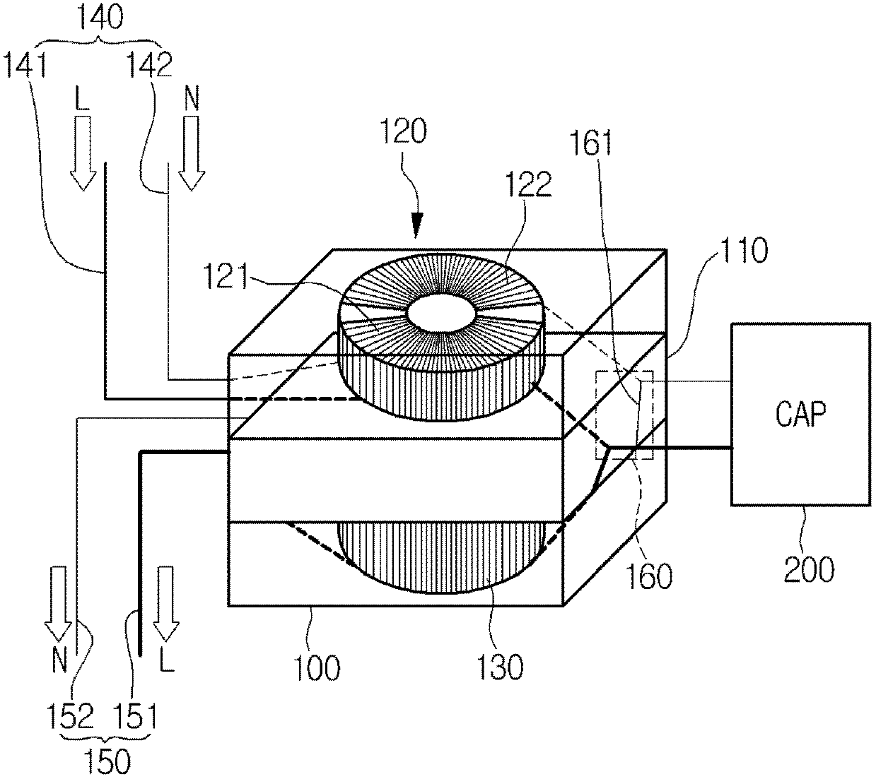
[0044] image 3 Is a view showing the structure of a two-stage linear filter 100 according to an embodiment.
[0045] Below, will refer to image 3 The two-stage linear filter 100 according to one embodiment is described in detail.
[0046] Such as image 3 As shown, the two-stage linear filter 100 according to this embodiment includes a bobbin 110, a first coil 120, a second coil 130, an input line 140, an output line 150, and a connecting line 160.
[0047] The bobbin 110 may have two surfaces, and a coil is wound around the two surfaces. In particular, the bobbin 110 may have vertically divided cores (not shown) formed on these surfaces so as to wind a coil around these surfaces.
[0048] For example, such as image 3 As shown, the core may be formed on the surface of the bobbin 100 such that the first coil 120 is wound around the top surface of the bobbin 100 and the second coil 130 is wound around the bottom surface of the bobbin 100.
[0049] At the same time, one end of the first coil 120 is connected to the input line 140 to which the alternating current is applied, and the opposite end corresponding to this end is connected to the connection line 160 for connecting the first coil 120 to the second coil 130.
[0050] In addition, one end of the second coil 130 is connected to the output line 150 for outputting noiseless alternating current, and the opposite end corresponding to the end connected to the output line 150 is connected to the connection line 160.
[0051] At the same time, the connecting wire 160 is placed between the first coil 120 and the second coil 130 to electrically connect the first coil 120 to the second coil 130 as described above. The connection line 160 includes a capacitor connection unit 161 so that the connection line 160 can be connected to the capacitor 200 for noise removal and filtering purposes.
[0052] The capacitor 200 may include various capacitors for linear filtering. Preferably, the capacitor 200 may include an X capacitor. Alternatively, the capacitor 200 may include a plurality of capacitors. In addition, the capacitor 200 may be connected to a circuit including various devices. Therefore, this embodiment is not limited to one capacitor.
[0053] At the same time, according to the two-stage linear filter of this embodiment, the input line 140 for inputting AC power includes a live line 141 and a neutral line 142. Therefore, the first coil 120 may include a first input coil 121 and a second input coil 122 corresponding to the live wire 141 and the neutral wire 142.
[0054] The first input coil 121 is connected to the live wire 141 for inputting electric power and is connected to the second coil 130 through the connection wire 160. Therefore, the first input coil 121 may perform a linear filtering operation on the power input through the live wire 141 and may output the filtered input power to the second coil 130 through the capacitor 200.
[0055] In addition, the second input coil 122 is connected to the neutral line 142 for inputting power and is connected to the second coil 130 through the connection line 160. Except for replacing the live wire 141 with the neutral wire 142, the second input coil 122 has the same function as the first input coil 121.
[0056] At the same time, similar to the input line 140, the output line 150 of the integral two-stage linear filter according to one embodiment includes a live line 151 and a neutral line 152. Therefore, the second coil 130 may include a first output coil 131 and a second output coil 132 corresponding to the live wire 151 and the neutral wire 152, respectively.
[0057] One end of the first output coil 131 is connected to the first coil 120 through the connecting wire 160, and the opposite end corresponding to the end is connected to the live wire 151 of the output wire 150. Therefore, the first output coil 131 may perform a quadratic linear filtering operation on the power input from the first coil 120 through the connection line 160 and output the filtered power through the live wire 151 of the output line 150.
[0058] In addition, as described above, one end of the second output coil 132 is connected to the first coil 120 through the connection line 160, and the opposite end corresponding to this end is connected to the neutral line 152 of the output line 150. Therefore, the second output coil 132 may perform a quadratic linear filtering operation on the power input from the first coil 120 through the connection line 160 and output the filtered power through the neutral line 152 of the output line 150.
[0059] Meanwhile, the integral two-stage linear filter according to one embodiment may include a housing that supports the linear filter and is used for mounting on the inverted substrate. The housing covers the side of the bobbin 100, thereby preventing the bobbin 100 from shaking, and at the same time preventing interference of separated peripheral components caused by external vibration of the electrical appliance or interference of wires disposed adjacent to the coils 120 and 130.
[0060] In addition, the housing is provided with a connector (not shown) on one side thereof, and the connector connects the live line 141 and the neutral line 142 of the input line 140 and the live line 151 and the neutral line 152 of the output line 150.
[0061] In this case, the connector may include four connectors for connecting the live line 141 and the neutral line 142 of the input line 140 and the live line 151 and the neutral line 152 of the output line 150, and may be sequentially arranged in one of the housings. Side. In addition, the connectors for the live line 141 and the neutral line 142 of the input line 140 are provided on one side of the housing, and the connectors for the live line 151 and the neutral line 152 of the output line 150 are provided on the opposite side of the housing, thereby The arrangement of wires and the pin connection of the input/output terminals can be easily performed. Alternatively, the live line 141 of the input line 140 and the live line 151 of the output line 150 are arranged on one side of the housing, and the neutral line 142 of the input line 140 and the neutral line 152 of the output line 150 may be arranged on opposite sides of the housing.
[0062] The connector arrangement of the housing facilitates pin connection and wire arrangement. For example, connectors for the input line 140 and the output line 150 may be provided on one side of the housing. Accordingly, a connector for the capacitor 200 may be additionally provided on the opposite side of the case, so that the capacitor 200 may be connected to the capacitor connection unit 161.
[0063] Figure 4 It is a view showing a structure in which the integrated two-stage linear filter 110 according to an embodiment is coupled with a substrate.
[0064] Such as Figure 4 As shown, the integral two-stage linear filter 110 may be installed in the aforementioned housing and then coupled with the substrate.
[0065] The bobbin 110 has a structure in which coils are wound around both surfaces thereof, and the bobbin 110 is provided with a core on the top surface thereof, and a first input coil 121 and a second input coil 122 are wound around the core. In this case, the bobbin 110 is additionally provided on the top surface thereof with a protruding part 170 that separates the first input coil 121 from the second input coil 122.
[0066] Similarly, the bobbin 110 is provided on its bottom surface with a protruding part 171 that separates the first output coil 131 from the second output coil 132.
[0067] Figure 5 It is a view showing a method of manufacturing an integrated two-stage linear filter 100 according to another embodiment.
[0068] Reference Figure 5 , The bobbin 110 of the integral two-stage linear filter 100 according to one embodiment can be configured by combining the first bobbin 111 for winding the first coil 120 and the second winding bobbin for winding the second coil 130 The bobbin 112 is formed by being vertically coupled. For the purpose of coupling, coupling units 181 and 182 may be provided in the first bobbin 111 and the second bobbin 112 or in the housing to connect the first bobbin 111 and the second bobbin corresponding to their positions. The spool 112 is fixed.
[0069] Image 6 It is a view showing a process in which the integrated two-stage linear filter 100 according to an embodiment is coupled with a PCB substrate.
[0070] Reference Image 6 , The integral two-stage linear filter 100 may be fixed to the housing and may be fixed to the PCB substrate through the coupling unit 190 formed in the housing. For the purpose of fixing, a perforating process is required at the relevant position of the PCB substrate, and the fixed integral two-stage linear filter 100 is completely coupled through the insertion process.
[0071] As mentioned above, one-step execution will Image 6 The shown process of fixing the integrated two-stage linear filter 100 to the PCB substrate can reduce the perforation and insertion process in which the conventional two-stage linear filter is coupled to the PCB substrate by half.
[0072] At the same time, the above-mentioned integral two-stage linear filter 100 is included in the AC power supply to remove the noise of the AC power. According to the present disclosure, the integral two-stage linear filter 100 is inserted into the input terminal or the output terminal of the AC power source to remove the noise of the AC power.
[0073] The method of manufacturing the integral two-stage linear filter 100 according to the present disclosure includes the steps of forming a bobbin 110 having two surfaces wound with coils, and winding the first coil 120 around the first surface of the bobbin 110. The step of connecting a coil 120 to the input line 140 and connecting the first coil 120 to the second coil 130 through the connecting line 160 and forming a capacitor connection unit 161 on the connecting line 160 to filter the alternating current passing through the first coil 120 and The step of transmitting the alternating current to the second coil 130.
[0074] As described above, according to the integral two-stage linear filter 100, the AC power supply including the integral two-stage linear filter 100, and the method of manufacturing the integral two-stage linear filter 100 according to an embodiment, it is possible to A two-stage linear filter is implemented in a space where one linear filter is arranged, so that the cost of raw materials can be reduced when compared with a conventional two-stage linear filter having two linear filters arranged successively.
[0075] In addition, according to the integral two-stage linear filter 100 of one embodiment, the number of processes for manufacturing the two-stage linear filter and coupling the two-stage linear filter to the PCB can be reduced, and the size of the PCB board can be reduced.
[0076] Although the embodiments have been described with reference to a number of illustrated embodiments thereof, it should be understood that those skilled in the art may conceive of various other modifications and embodiments that will fall within the spirit and scope of the principles of the present disclosure. More specifically, various changes and modifications in the component parts and/or arrangement of the subject combination arrangement are possible within the scope of the appended claims, drawings and the present disclosure. In addition to changes and modifications in component parts and/or arrangement, those skilled in the art will also understand alternative uses.

PUM

no PUM

Description & Claims & Application Information

We can also present the details of the Description, Claims and Application information to help users get a comprehensive understanding of the technical details of the patent, such as background art, summary of invention, brief description of drawings, description of embodiments, and other original content. On the other hand, users can also determine the specific scope of protection of the technology through the list of claims; as well as understand the changes in the life cycle of the technology with the presentation of the patent timeline. Login to view more.

Similar technology patents

Magnetically guided catheter

ActiveUS20100174177A1low costhigh performance
Owner:ST JUDE MEDICAL ATRIAL FIBRILLATION DIV

Material including graphene and an inorganic material and method of manufacturing the material

ActiveUS20110129675A1reduce defectlow cost
Owner:SAMSUNG ELECTRONICS CO LTD +1

Classification and recommendation of technical efficacy words

  • Save PCB area
  • low cost

Structure and Method for Power Field Effect Transistor

ActiveUS20100301496A1save PCB areathin contour
Owner:TEXAS INSTR INC

Television with multiplexing of USB (Universal Serial Bus) interface and method for multiplexing USB interface

InactiveCN102655577ASave PCB arealow cost
Owner:XIAMEN OVERSEAS CHINESE ELECTRONICS ENTERPRISE

Constant-current control circuit for isolated switching power supply

ActiveCN102255507ASimple structureSave PCB area
Owner:MAXIC TECHNOLOGY CORPORATION

OCT spectral signal acquisition and transmission system based on ZYNQ

InactiveCN110336928ASave PCB areaWide applicability
Owner:ZHEJIANG UNIV OF TECH

System and method for transmitting wireless digital service signals via power transmission lines

ActiveUS7929940B1reduce bandwidth requirementlow cost
Owner:NEXTEL COMMUNICATIONS

Plastic waveguide-fed horn antenna

InactiveUS20100214185A1low cost
Owner:RGT UNIV OF CALIFORNIA

System and method for determination of position

InactiveUS20090149202A1low costreduce requirement
Owner:STEELE CHRISTIAN

Adaptive antenna optimization network

InactiveUS6961368B2low costminimal space
Owner:ERICSSON INC
Why Eureka
Try Eureka