Valve for controlling fluids

A technology for controlling fluid and valve seat, applied in the direction of lifting valve, valve device, brake, etc., can solve the problems of small construction space, increase of flow resistance, decrease of valve flow rate, etc., and achieve the effect of improving flow and reducing separation

Active Publication Date: 2013-05-15
ROBERT BOSCH GMBH
View PDF4 Cites 2 Cited by
  • Summary
  • Abstract
  • Description
  • Claims
  • Application Information

AI Technical Summary

Problems solved by technology

As a result, flow resistance increases even with the valve open, resulting in a reduction in valve flow
However, the construction of the valves in such braking devices should be as small and compact as possible, so as to take up as little construction space as possible

Method used


Image

  • Valve for controlling fluids
  • Valve for controlling fluids
  • Valve for controlling fluids

Examples


Embodiment Construction

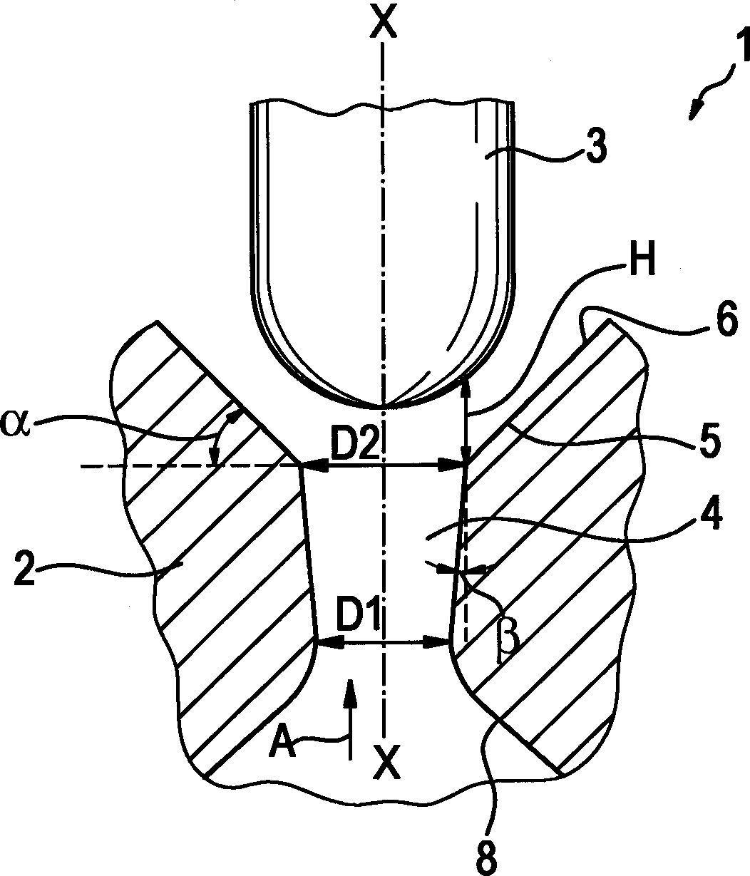
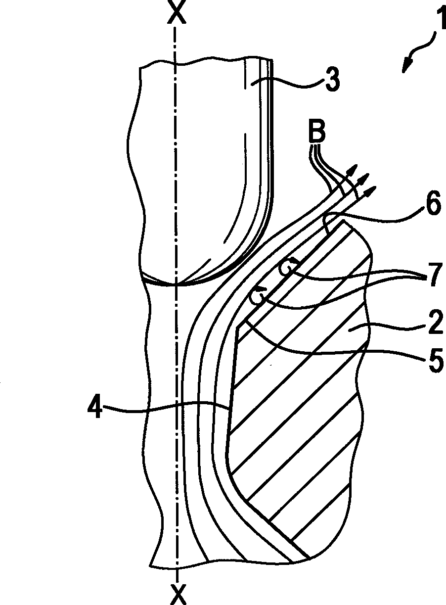
[0017] The following will refer to Figures 1 to 3 A valve 1 for controlling fluid is specifically described. The valve 1 is used as a distribution valve in a brake safety system of a motor vehicle.

[0018] like figure 1 As shown, the valve 1 comprises a valve element 2 with a through hole 4 and a valve seat 5 formed on the valve element 2 . The valve seat 5 is formed on a first conical region 6 of the valve element. The closing member 3 is semicircular and seals on the valve seat 5 .

[0019] like figure 1 As shown, the through-opening 4 has a shape that widens in the flow direction A of the valve 1 . In this exemplary embodiment, the through-opening 4 widens conically. At the same time, the angle β between the through hole and the parallel line of the central axis X-X is 7.5°. Here, the minimum diameter D1 of the through hole and the maximum diameter D2 of the through hole are selected such that the ratio of the minimum diameter D1 to the maximum diameter D2 is 0.78....


PUM


Abstract

The present invention relates to a valve for controlling fluids with an improved flow behaviour, comprising a valve element (2) with a through opening (4) and a valve seat (5), wherein the valve seat (5) is formed on a first conical region (6) of the valve element (2), and a closing element (3) which opens and closes the through opening (4) at the valve seat (5), wherein the through opening (4) has a shape which widens in the flow direction (H).

Description

technical field [0001] The invention relates to a valve for controlling fluids with improved flow characteristics and to a braking device with such a valve. Background technique [0002] Valves for controlling fluids are known in various designs from the prior art. In the current application of valves in vehicle brake systems, 2 / 2-way valves are used as hydraulic valves. Here, a certain minimum flow must be reached with a predetermined lift and a predetermined differential pressure. The known valve has a through-opening embodied in the shape of a cylinder. It can be determined here that in the operating state when the valve is open a flow separation can develop in the valve seat. This flow separation leads to a considerable reduction of the flow cross-section, which deviates significantly from the theoretical geometric cross-section. Therefore, flow resistance increases even with the valve open, resulting in a decrease in valve flow. However, the design of the valve in ...

Claims


Application Information

Patent Timeline
Patent Type & Authority Applications(China)
IPC IPC(8): F16K1/42
CPCF16K1/38F16K1/42B60T8/3615
Inventor N·霍伊斯
Owner ROBERT BOSCH GMBH
Why Eureka
Try Eureka