Heating container of water dispenser and control method thereof

A technology of water dispenser and hot water tank, which is applied in the field of water dispenser components, can solve the problems of easy dry burning protection, lower outlet water temperature, and faster drop of outlet water temperature, and achieve improved safety, accurate water temperature control, and simple control method practical effect

Inactive Publication Date: 2013-05-22
ELECTROTEMP TECHNOLOGIES CHINA INC
View PDF6 Cites 10 Cited by
  • Summary
  • Abstract
  • Description
  • Claims
  • Application Information

AI Technical Summary

Problems solved by technology

[0003] The purpose of the present invention is to overcome the existence of the electric heater installed in the inner cavity of the hot water dispenser, which is difficult to effectively protect the dry burning damage and the cold water will directly flow to the outlet pipe after entering the hot water pipe from the water inlet pipe. Insufficient to reduce the temperature of the outlet water quickly, provide an electric heater that can effectively protect the water dispenser that is not easy to be damaged by dry burning and the cold water will not flow directly to the outlet pipe after entering the hot tank from the inlet pipe, so that the temperature of the outlet water can be lowered slowly Heat bladder and control method

Method used


Image

  • Heating container of water dispenser and control method thereof
  • Heating container of water dispenser and control method thereof
  • Heating container of water dispenser and control method thereof

Examples


Embodiment 1

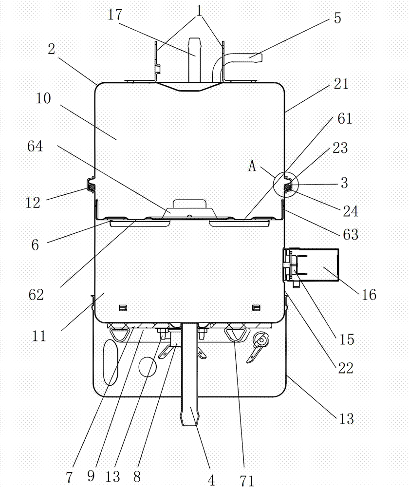
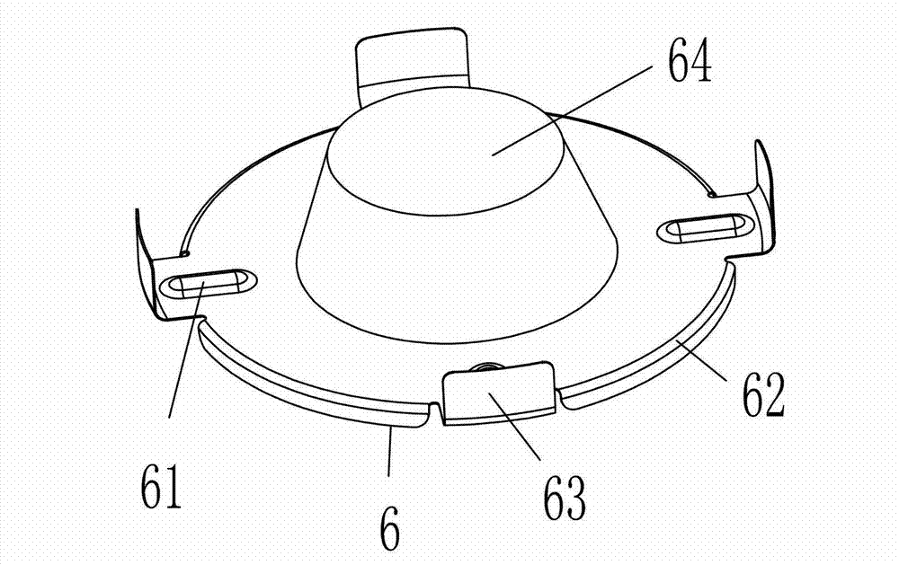
[0028] Embodiment 1, as attached figure 1 , attached image 3 , attached Figure 4 Shown: a water dispenser heat tank, including a heat tank body 2, a mounting bracket 1 welded to the upper end of the heat tank body 2, two water temperature thermostats for controlling the water temperature in the heat tank body 2, a water inlet pipe 4, and an outlet pipe The water pipe 5, the buffer plate 6 that is located in the inner wall of the thermal bladder body 2 and the outer circumference is screwed to the inner circumference of the thermal bladder body 2, the electric heating plate 7 that has a heating element 71 and is welded with the lower end of the thermal bladder body 2, is fixed by screws The set temperature on the electric heating plate 7 is higher than the high-temperature thermostat 8 of the boiling point of water and the temperature fuse 9 whose fusing temperature is higher than the set temperature of the high-temperature thermostat 8; The interior is divided into an uppe...

Embodiment 2

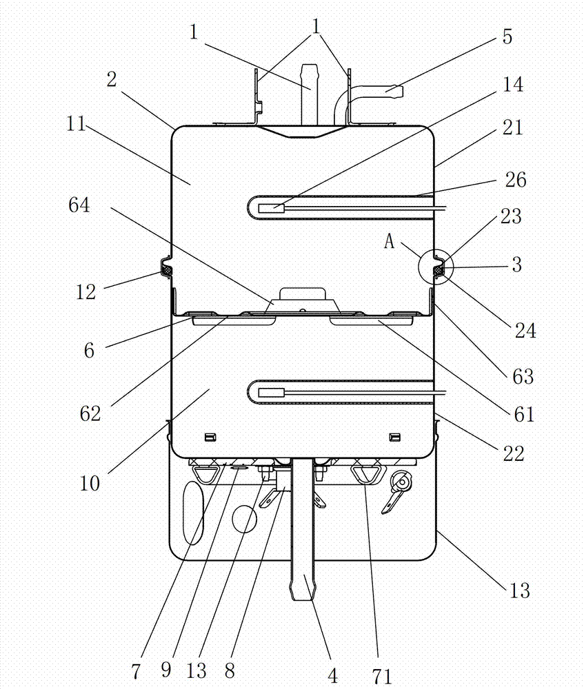
[0041] Embodiment 2, as attached figure 2 , attached image 3 , attached Figure 4 Shown: a water dispenser heat tank, including a heat tank body 2, a mounting bracket 1 welded to the upper end of the heat tank body 2, two water temperature thermostats for controlling the water temperature in the heat tank body 2, a water inlet pipe 4, and an outlet pipe The water pipe 5, the buffer plate 6 which is fixedly connected to the inner side of the inner circumference of the outer wall and the thermal inner body 2, the electric heating plate 7 with the heating element 71 and welded with the lower end of the hot inner body 2, are fixed by screws The set temperature on the electric heating plate 7 is higher than the high-temperature thermostat 8 of the boiling point of water and the temperature fuse 9 whose fusing temperature is higher than the set temperature of the high-temperature thermostat 8; The interior is divided into an upper chamber 10 and a lower chamber 11; the buffer pl...


PUM


Abstract

The invention relates to the field of accessories of a water dispenser and provides a heating container of the water dispenser and a control method thereof. The heating container of the water dispenser comprises a heating container body, an installation support fixedly connected at the upper end of the heating container body, at least one water temperature control device for controlling temperature of water inside the heating container body, a water inlet pipe, a water outlet pipe, a buffer disk located in the heating container body and fixedly connected with the inner side of the heating container body, an electric heating disk provided with a heating element and fixedly connected with the lower end of the heating container body, a high temperature controller and a temperature fuse, wherein the high temperature controller and the temperature fuse are fixed on the electric heating disk, the buffer disk divides the heating container body into an upper cavity and a lower cavity and is provided with a plurality of through holes, the water inlet pipe is communicated with the upper cavity, and the water outlet pipe is communicated with the lower cavity. An electric heater of the heating container of the water dispenser can be effectively protected, not prone to dry burning and be damaged, and cold water can not directly flow to the water outlet pipe after entering the heating container body through the water inlet pipe so that water outlet temperature decreases slowly. The control method of the heating container of the water dispenser is simple, practical and good in safety.

Description

technical field [0001] The invention relates to the field of water dispenser components, in particular to a water dispenser heater and a control method. Background technique [0002] The utility model of Chinese patent notification number CN2913942Y discloses a water dispenser hot tank, which includes a cylindrical hot tank body and a water inlet pipe, an outlet pipe and an exhaust pipe communicated with the inner cavity of the hot tank body, and the outer wall of the hot tank body A mounting bracket is fixedly connected to it, and an electric heater and a temperature controller are also installed in the inner cavity of the thermal bladder, and the power connector of the electric heater extends out of the inner cavity of the thermal bladder, and the The outer body of the thermal body is wrapped with a polyurethane insulation layer. The heater of the water dispenser has an electric heater installed in the inner cavity of the heater body, which is difficult to effectively pro...

Claims


Application Information

Patent Timeline
Patent Type & Authority Applications(China)
IPC IPC(8): A47J31/56A47J31/58
Inventor 于乔治
Owner ELECTROTEMP TECHNOLOGIES CHINA INC
Why Eureka
Try Eureka