Multifunctional assembly and disassembly equipment for parts of dynamical system of new energy vehicles
What is AI technical title?
AI technical title is built by PatSnap AI team. It summarizes the technical point description of the patent document.
A new energy vehicle and power system technology, which is applied in the field of multifunctional disassembly and assembly equipment for new energy vehicle power system components, can solve the problems of inability to meet the disassembly and assembly requirements of new energy vehicle power system components, poor safety and stability, and complicated disassembly and assembly. , to achieve the effect of ingenious design, accurate and convenient disassembly and assembly, and simplified installation process
Inactive Publication Date: 2013-05-22
JIANGXI B ENERGY SHANGRAO COACH
View PDF9 Cites 22 Cited by
Summary
Abstract
Description
Claims
Application Information
AI Technical Summary
This helps you quickly interpret patents by identifying the three key elements:
Problems solved by technology
Method used
Benefits of technology
Problems solved by technology
At present, the disassembly and assembly of power components of such new energy vehicles is complicated, requires more manpower, and has poor safety and stability
After searching, we found several patent documents about traditional automobile gearbox disassembly equipment, such as "lifter for disassembly and assembly of gearbox (CN 201049873Y)", "lifter for assembly and disassembly of automobile gearbox assembly (CN 2258866Y)", etc. These devices Although it facilitates the disassembly and assembly of the gearbox to a certain extent, it has a single function and cannot meet the disassembly and assembly requirements of new energy vehicle power system components.
Method used
Image
Click on the blue label to locate the original text in one second.
Reading with bidirectional positioning of images and text.
Examples
Embodiment Construction
[0033] In order to understand the technical content of the present invention more clearly, the following examples are given in detail. In this case, the same components are provided with the same reference numerals.
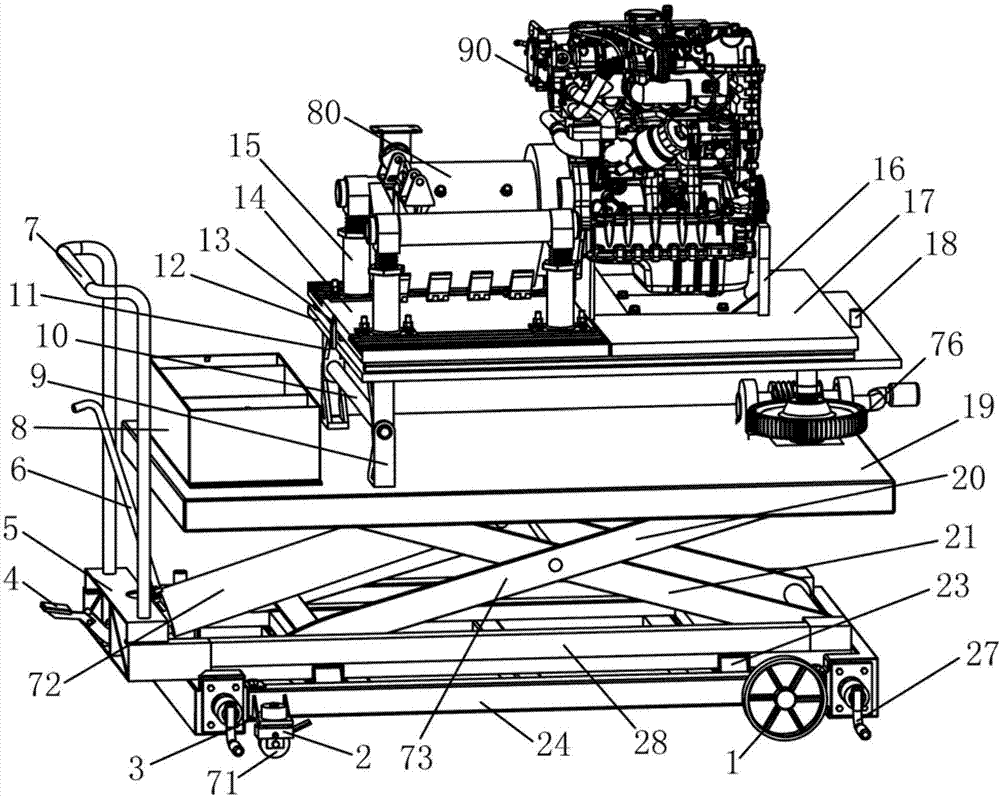
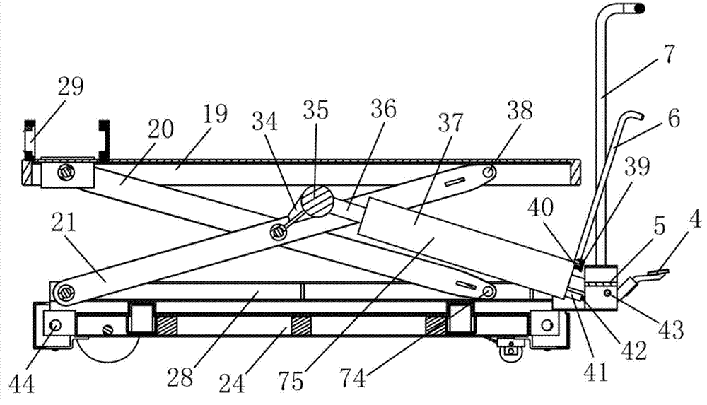
[0034] See Figure 1-Figure 5 As shown, the multifunctional disassembly and assembly equipment for new energy vehicle power system components of the present invention includes a bottom wheel 1, a chassis 24, a subframe 28, a top plate 19, a support platform 12, a motor bracket installation platform 14, and a replaceable bracket installation platform 17. Motor support 15 and replaceable support 16, the bottom wheel 1 is rotatably installed under the chassis 24 and supports the chassis 24, and the sub-frame 28 is supported on the chassis 24 and opposite to the chassis 24 is movable left and right, the top plate 19 is supported on the sub-frame 28 and is movable up and down relative to the sub-frame 28, and the support platform 12 is rotatably set on the top plate ...
PUM
Abstract
The invention relates to a multifunctional assembly and disassembly equipment for parts of a dynamical system of new energy vehicles. Bottom wheels can be rotatably installed beneath a chassis and support the chassis. An auxiliary vehicle frame is supported on the chassis and is arranged in a left and right moving mode relative to the chassis. A top plate is supported on the auxiliary vehicle frame and is arranged in an up and down moving mode relative to the auxiliary vehicle frame. A support platform is rotatably arranged on the top plate by rotating around the rear end. A motor support installation platform and a replaceable support installation platform are arranged adjacent to each other and are both arranged on the support platform in a front and back moving mode. A motor support is arranged on the motor support installation platform, a replaceable support is arranged on the replaceable support installation platform, and the replaceable support is an engine support or a gearbox support. The multifunctional assembly and disassembly equipment for parts of the dynamical system of new energy vehicles is ingenious in design, enables assembly and disassembly of parts of the dynamical system of new energy vehicles to be accurate, simple and convenient, greatly simplifies an installation process, reduces investment on manpower and material resources, decreases the number of times of adjustment, greatly improves work efficiency and is suitable for large-scale popularization and application.
Description
technical field [0001] 本发明涉及拆装设备技术领域,特别涉及新能源汽车动力系统部件的拆装设备技术领域,具体是指一种新能源汽车动力系统部件的多功能拆装设备。 Background technique [0002] 以动力电池作为动力源的新能源汽车的动力系统部件和传统汽车最大不同是多了电机或没有发动机,所以动力部件拆装设备、方法与传统汽车有很大的不同;而现在这类汽车的动力部件拆装还没有一套成熟、可靠、方便的设备。目前,此类新能源汽车的动力部件拆装复杂、需要较多的人力且安全稳定性较差。经检索发现几篇关于传统汽车变速箱拆装设备的专利文献,如“变速箱拆装用升降器(CN 201049873Y)”、“汽车变速箱总成装卸提升器(CN 2258866Y)”等,这些设备虽然在一定程度上方便了变速箱的拆装,但是功能单一且不能满足新能源汽车动力系统部件的拆装要求。 [0003] 因此,需要提供一种新能源汽车动力系统部件的拆装设备,使得新能源汽车动力系统部件的拆装准确简便,大大简化安装过程,降低人力物力的投入,减少调整次数,大大提高工作效率。 Contents of the invention [0004] 本发明的目的是克服了上述现有技术中的缺点,提供一种新能源汽车动力系统部件的多功能拆装设备,该新能源汽车动力系统部件的多功能拆装设备设计巧妙,使得新能源汽车动力系统部件的拆装准确简便,大大简化安装过程,降低人力物力的投入,减少调整次数,大大提高工作效率,适于大规模推广应用。 [0005] 为了实现上述目的,本发明的新能源汽车动力系统部件的多功能拆装设备,其特点是,包括底部车轮、底盘、副车架、顶盘、支撑平台、电机支架安装平台、可更换支架安装平台、电机支架和可更换支架,所述底部车轮可转动安装在所述底盘下并支撑所述底盘,所述副车架支撑在所述底盘上并相对所述底盘左右可移动设置,所述顶盘支撑在所述副车架上并相对所述副车架上下可移动设置,所述支撑平台绕其后端可转动设置在所述顶盘上,所述电机支架安装平台和所述可更换支架安装平台相邻设置并均前后可移动设置在所述支撑平台上,所述电机支架安设在所述电机支架安装平台上,所述可更换支架安设在所述可更换支架安装平台上,所述可更换支架是发动机支架或变速箱支架。 [0006] 较佳地,所述底部车轮包...
Claims
Application Information
Patent Timeline
Application Date:The date an application was filed.
Publication Date:The date a patent or application was officially published.
First Publication Date:The earliest publication date of a patent with the same application number.
Issue Date:Publication date of the patent grant document.
PCT Entry Date:The Entry date of PCT National Phase.
Estimated Expiry Date:The statutory expiry date of a patent right according to the Patent Law, and it is the longest term of protection that the patent right can achieve without the termination of the patent right due to other reasons(Term extension factor has been taken into account ).
Invalid Date:Actual expiry date is based on effective date or publication date of legal transaction data of invalid patent.

