Multifunctional assembly and disassembly equipment for parts of dynamical system of new energy vehicles

A new energy vehicle and power system technology, which is applied in the field of multifunctional disassembly and assembly equipment for new energy vehicle power system components, can solve the problems of inability to meet the disassembly and assembly requirements of new energy vehicle power system components, poor safety and stability, and single function. Achieve the effects of ingenious design, accurate and convenient disassembly and assembly, and simplified installation process

Inactive Publication Date: 2015-04-22
JIANGXI B ENERGY SHANGRAO COACH
View PDF2 Cites 0 Cited by
  • Summary
  • Abstract
  • Description
  • Claims
  • Application Information

AI Technical Summary

Problems solved by technology

At present, the disassembly and assembly of power components of such new energy vehicles is complicated, requires more manpower, and has poor safety and stability
After searching, we found several patent documents about traditional automobile gearbox disassembly equipment, such as "lifter for disassembly and assembly of gearbox (CN 201049873Y)", "lifter for assembly and disassembly of automobile gearbox assembly (CN 2258866Y)", etc. These devices Although it facilitates the disassembly and assembly of the gearbox to a certain extent, it has a single function and cannot meet the disassembly and assembly requirements of new energy vehicle power system components.

Method used


Image

  • Multifunctional assembly and disassembly equipment for parts of dynamical system of new energy vehicles
  • Multifunctional assembly and disassembly equipment for parts of dynamical system of new energy vehicles
  • Multifunctional assembly and disassembly equipment for parts of dynamical system of new energy vehicles

Examples


Embodiment Construction

[0033] In order to understand the technical content of the present invention more clearly, the following examples are given in detail. In this case, the same components are provided with the same reference numerals.

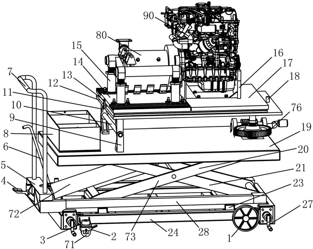
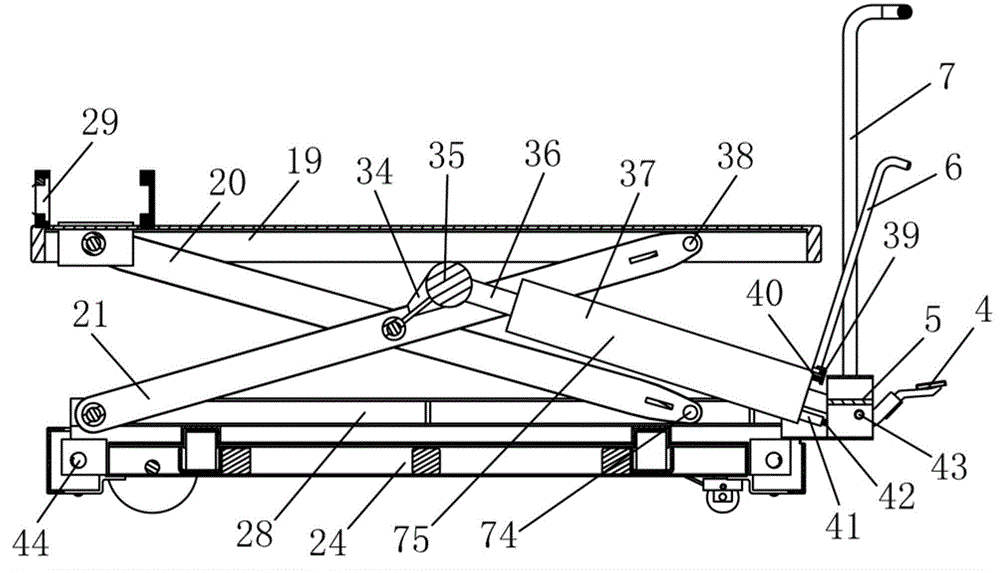
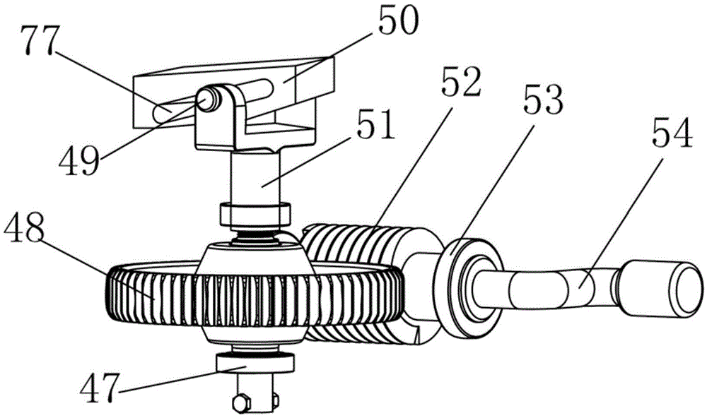
[0034] See Figure 1-Figure 5 As shown, the multifunctional disassembly and assembly equipment for new energy vehicle power system components of the present invention includes a bottom wheel 1, a chassis 24, a subframe 28, a top plate 19, a support platform 12, a motor bracket installation platform 14, and a replaceable bracket installation platform 17. Motor support 15 and replaceable support 16, the bottom wheel 1 is rotatably installed under the chassis 24 and supports the chassis 24, and the sub-frame 28 is supported on the chassis 24 and opposite to the chassis 24 is movable left and right, the top plate 19 is supported on the sub-frame 28 and is movable up and down relative to the sub-frame 28, and the support platform 12 is rotatably set on the top plate ...


PUM


Abstract

The invention relates to a multifunctional assembly and disassembly equipment for parts of a dynamical system of new energy vehicles. Bottom wheels can be rotatably installed beneath a chassis and support the chassis. An auxiliary vehicle frame is supported on the chassis and is arranged in a left and right moving mode relative to the chassis. A top plate is supported on the auxiliary vehicle frame and is arranged in an up and down moving mode relative to the auxiliary vehicle frame. A support platform is rotatably arranged on the top plate by rotating around the rear end. A motor support installation platform and a replaceable support installation platform are arranged adjacent to each other and are both arranged on the support platform in a front and back moving mode. A motor support is arranged on the motor support installation platform, a replaceable support is arranged on the replaceable support installation platform, and the replaceable support is an engine support or a gearbox support. The multifunctional assembly and disassembly equipment for parts of the dynamical system of new energy vehicles is ingenious in design, enables assembly and disassembly of parts of the dynamical system of new energy vehicles to be accurate, simple and convenient, greatly simplifies an installation process, reduces investment on manpower and material resources, decreases the number of times of adjustment, greatly improves work efficiency and is suitable for large-scale popularization and application.

Description

technical field [0001] The invention relates to the technical field of assembly and disassembly equipment, in particular to the technical field of assembly and disassembly equipment for power system components of new energy vehicles, and specifically refers to a multifunctional equipment for disassembly and assembly of power system components of new energy vehicles. Background technique [0002] The biggest difference between the power system components of new energy vehicles with power batteries as the power source and traditional vehicles is that there are more motors or no engines, so the disassembly equipment and methods of power components are very different from traditional vehicles; There is not yet a set of mature, reliable and convenient equipment for the disassembly and assembly of power components. At present, the disassembly and assembly of power components of such new energy vehicles is complicated, requires more manpower, and has poor safety and stability. Aft...

Claims


Application Information

Patent Timeline
Patent Type & Authority Patents(China)
IPC IPC(8): B25H1/04B25H1/16B25H1/18
Inventor 刘楠祝景峰程明福
Owner JIANGXI B ENERGY SHANGRAO COACH
Why Eureka
Try Eureka