Supercharge Your Innovation With Domain-Expert AI Agents!

Locking device for ball screw

A technology of ball screw and locking device, which is applied in the direction of transmission device, belt/chain/gear, mechanical equipment, etc. It can solve the problems of not being able to meet the requirements, and cannot guarantee the safety of pilots, etc., and achieve good results and solve the self-locking function. Effect

Active Publication Date: 2015-12-09
HARBIN DONGAN ENGINE GRP
View PDF4 Cites 0 Cited by
  • Summary
  • Abstract
  • Description
  • Claims
  • Application Information

AI Technical Summary

Problems solved by technology

However, the structure of the ball screw pair cannot be self-locking, and it cannot prevent the screw nut from rotating at the moment of ejection of the lifesaving seat of the aircraft. It is easy to cause a major accident, so it cannot meet the requirements of the ejection of the lifesaving seat, and cannot guarantee the safety of the pilot's life.

Method used


Image

  • Locking device for ball screw

Examples


Embodiment Construction

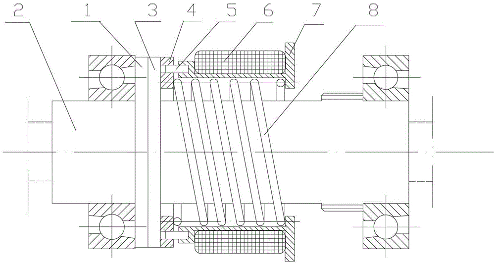
[0007] As shown in the figure, the locking device of the ball screw includes a housing 7, a coil 6, a screw nut 2, a brake disc 4, and a pressure spring 8. The coil 6 is installed on the housing 7, and a pressure spring is provided inside the housing 7. Spring 8, the housing 7 is also equipped with a brake disc 4 that can move along the guide pin 5 through the guide pin 5, the axis of the brake disc 4 coincides with the axis of the ball screw, and the pressure spring 8 One end is pressed on the housing 7, and the other end is pressed on the brake disc 4. The end surface of the nut 2 of the ball screw is provided with a friction disc 1, and the end face of the brake disc 4 is provided with a friction disc with the end face of the nut 2. 1 corresponds to the friction disc 3.

[0008] In use, the coil 6 is connected in series with the motor of the electric mechanism. When the power is turned on, the coil 6 generates a magnetic field, and the brake disc 4 moves along the guide pin...


PUM


Abstract

The invention relates to a locking device of a ball screw. The locking device comprises a shell body (7), a coil (6), a screw nut (2), a brake disc (4) and a pressure spring (8). The coil (6) is arranged on the shell body (7), and the pressure spring (8) is arranged in the shell body (7). The shell body (7) is provided with the brake disc (4) which can move along a guide post pin and pass through the guide post pin (5). The axis of the brake disc (4) is in coincidence with that of the ball screw. One end of the pressure spring (8) is pressed on the shell body (7), and the other end of the pressure spring (8) is pressed on the brake disc (4). A friction disc (1) is arranged on the end face of the screw nut (2) of the ball screw, and a friction disc (3) corresponding to the friction disc (1) arranged on the end face of the screw nut (2) is arranged on the end face of the brake disc (4). Through action of the electromagnetic force and the pressure spring, moving and locking of the ball screw are realized, and a self-lock function of the ball screw is realized, and effect is good in actual application.

Description

technical field [0001] The invention relates to a locking device, in particular to a locking device for a ball screw. Background technique [0002] The electric mechanism of the aircraft rescue seat is used to adjust the lift of the seat pan, thereby controlling the position of the aircraft rescue seat. In the traditional electric mechanism, the actuator that converts the motor torque into linear motion usually adopts screw transmission, which has low transmission efficiency, large volume and weight, and high energy consumption. According to this situation, a structure using a ball screw pair is designed to replace the screw drive. This structure changes the sliding friction of the original screw drive to rolling friction, which reduces the friction force and requires less power. The efficiency is increased by 3 times, and at the same time, the volume, weight and energy consumption of the electric mechanism are greatly reduced. However, the structure of the ball screw pair...

Claims


Application Information

Patent Timeline
Patent Type & Authority Patents(China)
IPC IPC(8): F16H25/22
CPCF16H25/2204F16H25/2454
Inventor 宋剑锋陈晓峰闫东胜刘亚琴胡红艳官伟李悦姚勇吉胡乃今
Owner HARBIN DONGAN ENGINE GRP
Features
  • R&D
  • Intellectual Property
  • Life Sciences
  • Materials
  • Tech Scout
  • Unparalleled Data Quality
  • Higher Quality Content
  • 60% Fewer Hallucinations
Learn More