A composite torsion test device and method for components

An experimental device and component technology, which is applied in the direction of applying stable torsion to test the strength of materials, etc., can solve the problems of difficult experiment, complicated experimental method, high finishing cost, etc., and achieve simple operation and control of the experimental process, experimental operation and control The effect of simplicity, operation and control

Inactive Publication Date: 2014-10-15
TIANJIN YUANZHUO AUTOMATION EQUIP MFG CO LTD
View PDF6 Cites 0 Cited by
  • Summary
  • Abstract
  • Description
  • Claims
  • Application Information

AI Technical Summary

Problems solved by technology

[0003]At present, due to the limitations of experimental devices and methods, there are many experiments on pure torsion, compression torsion, bending torsion or shear torsion, and research on compression bending shear There are few torsion or bending-shear-torsion composite torsion experiments, and the few existing composite torsion experiments still have the following main shortcomings: 1) The stress of the component does not match the stress state of the component during the actual earthquake
2) The experimental method is complicated, the experimental device is not scientific enough, and multi-point loading makes the operation and control difficult during the experiment
In order to simulate the influence of lateral and horizontal seismic motion on the performance of structural members, the main difficulties encountered by researchers in the process of developing composite torsion experimental devices and methods are: 1) The usual bending, shearing, compression and tension In the experiment, the force, component and support reaction force are in one plane, so the experimental device and method are relatively simple
In the torsion test, the force, component and support reaction force are not in the same plane, it is a space force, the experimental device and method are much more complicated, especially the research and development of the composite torsion experiment of components under the action of horizontal and horizontal earthquakes devices and methods are more difficult
In order to simulate that the component can not only be torsion but also can only deform horizontally and horizontally under the horizontal earthquake action, the composite torsion test so far adopts a constant vertical force applied to the top of the component through a vertical force jack to simulate the gravity of the structure. A constant horizontal force is applied through a horizontal jack in the center of the top to simulate the shear force and bending moment on the member during an earthquake, and a pair of equal-sized and directed On the contrary, the horizontal force with a certain distance between the action lines is used to simulate the torque on the component during the earthquake. Although such an experiment simulates that the component can be torsion and can only be deformed horizontally under the action of a horizontal horizontal earthquake, the disadvantage is that the experimental process requires Simultaneously controlling the four forces, the experiment is very difficult, and the force of the component does not match the force state of the component during the actual earthquake
2) So far, the torsional deformation of the composite torsion test member is realized through a spherical joint, but due to the large vertical load required for the structural test, there is no standard spherical joint that can withstand such a load, and the cost of finishing is high.
Therefore, the spherical joints that have not been finished are used in the experiments, which will inevitably bring about certain experimental errors.

Method used


Image

  • A composite torsion test device and method for components
  • A composite torsion test device and method for components
  • A composite torsion test device and method for components

Examples


Embodiment

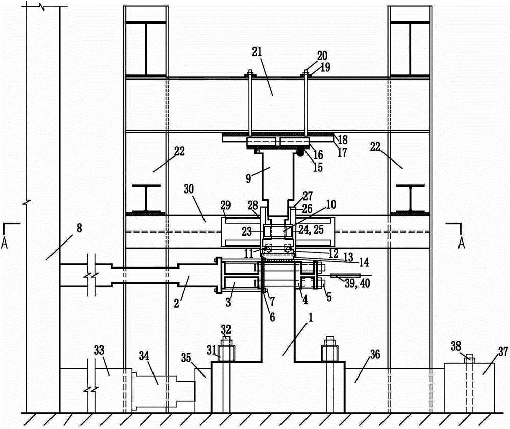
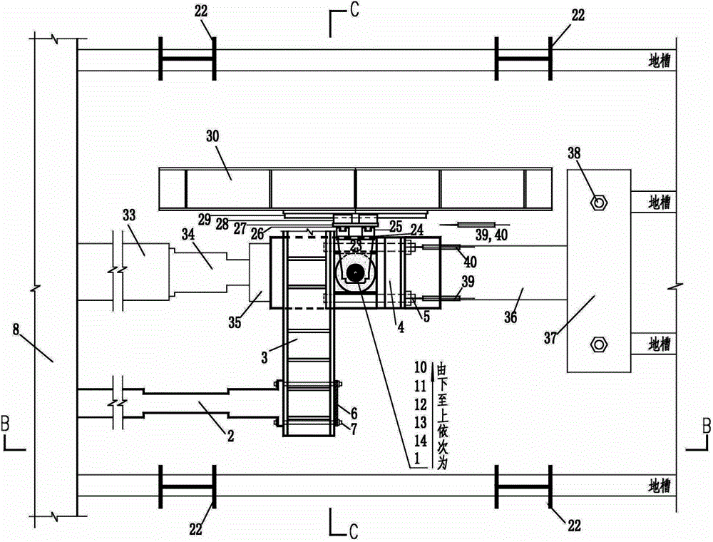
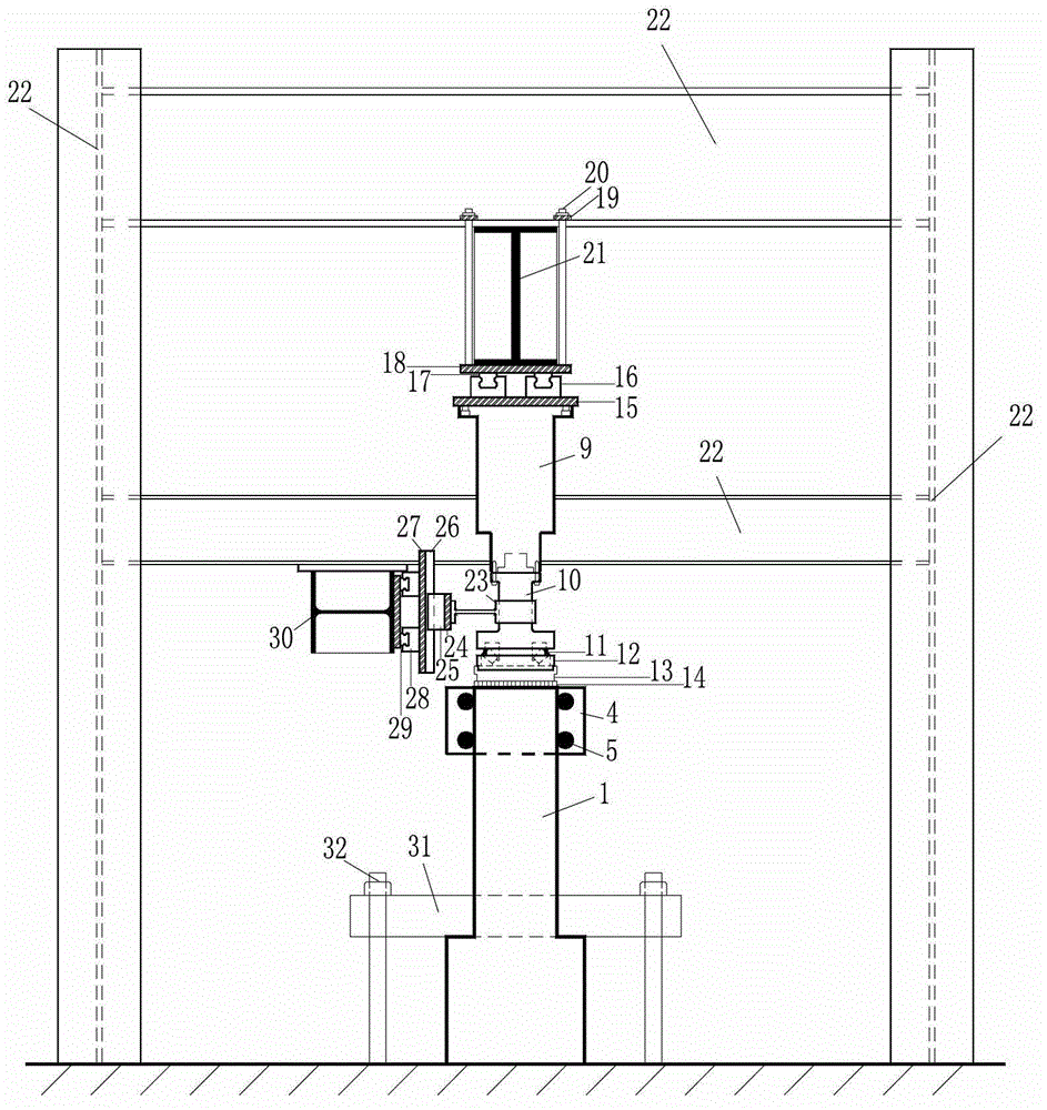
[0071] This embodiment provides an experimental device for compound torsion of structural members, and carried out the combined torsion experiment of compression bending, shear and torsion of 30 steel concrete members, and its structure is as follows figure 1 , figure 2 , image 3 As shown, it includes a horizontal force actuator 2, a loading beam 3, a clamping beam 4, a bolt 5 connecting the loading beam and the clamping beam, a steel plate 6 connecting the horizontal force actuator and the loading beam, and a bolt connecting the horizontal force actuator and the loading beam 7. Reaction wall 8. Vertical force jack 9. Adapter shaft connecting vertical force jack and thrust roller bearing 10. Thrust roller bearing 11. Mounting sleeve for the lower part of thrust roller bearing 12. Pressure bearing plate 13. Rubber pad 14, steel plate 15 connecting the vertical force jack and the slide block, slide block 16, guide rail 17, steel plate 18 for installing the guide rail, st...


PUM


Abstract

The invention discloses a compound torsion test device for components, which comprises two reaction frames fixed on the foundation floor, a reaction beam fixed at the upper end of the reaction frame at both ends, and a reaction beam fixed on the left side of the reaction beam The wall, the component is fixed on the foundation floor, is characterized in that it also includes a vertical force loading system for applying a vertical force to the component, a horizontal force loading system for applying a horizontal force to the component, and satisfies the axial deformation, bending deformation and shearing of the component. The top line displacement guide system of the component and the base displacement limiting system to fix the position of the component are required for shear deformation. The experimental device and method of the present invention overcome the shortcomings of the existing similar experimental devices and methods. The experimental principle is scientific, the operation and control of the experimental process are simple and convenient, the experimental device is easy to assemble, ready to use, and can be recycled. The composite torsional performance of structural components provides an experimental guarantee for revealing the composite torsional mechanism and seismic performance of structural components.

Description

technical field [0001] The invention belongs to the technical field of building structure experiments, and in particular relates to an experimental device and method for combined torsion of concrete components or steel-steel concrete components under the action of axial pressure. Background technique [0002] Torsion is one of the basic stress forms of structural members. If the load, member and support reaction force are not in the same plane, torque will be generated on the member section. Therefore, in civil engineering structures, members subject to torsion generally exist, but there are not many cases of pure torsion, and simple compound torsion such as compression torsion, bending torsion, or shear torsion. Force and torque (abbreviation: compression bending shear torsion) or bending moment, shear force and torque (abbreviation: bending shear torsion) combined torsion state, such as frame corner columns and other vertical members are usually in the combined compression...

Claims


Application Information

Patent Timeline
Patent Type & Authority Patents(China)
IPC IPC(8): G01N3/22
Inventor 邵永健曹晓罗孙宝强
Owner TIANJIN YUANZHUO AUTOMATION EQUIP MFG CO LTD
Why Eureka
Try Eureka