
Remote control chip for reducing frequency drift of inbuilt oscillating circuit

A technology for oscillating circuits and remote controls, applied to power oscillators, instruments, electrical components, etc., can solve problems such as RC drift of built-in oscillating circuits

Active Publication Date: 2015-06-17
SINO WEALTH ELECTRONICS
View PDF5 Cites 0 Cited by
  • Summary
  • Abstract
  • Description
  • Claims
  • Application Information

AI Technical Summary

Problems solved by technology

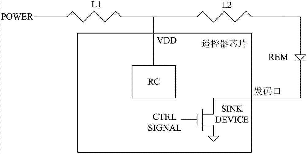
It is precisely because of the existence of the first inductance L1 and the second inductance L2 that the current of the remote control power supply POWER changes when the code sending control signal CTRL SIGNAL controls the code sending device SINK DEVICE from off to on and from on to off. Vigorously cause the chip power supply VDD to jitter, thus affecting the drift of the built-in oscillation circuit RC

Method used


Image

  • Remote control chip for reducing frequency drift of inbuilt oscillating circuit
  • Remote control chip for reducing frequency drift of inbuilt oscillating circuit

Examples


Embodiment Construction

[0022] Generally, the jitter on the power supply is divided into two situations: how large the amplitude of the jitter is and how long the time for maintaining the jitter is. The present invention performs debounce processing for these two situations.

[0023] 1. Debounce of jitter in amplitude

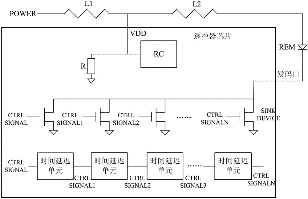
[0024] By opening the code sending device of the code sending port of the remote control chip step by step, reducing the current change rate of the code sending port, the amplitude of the jitter on the power supply can be reduced.

[0025] Under normal circumstances, the jitter amplitude on the power supply can be reduced from about 14V to below 6V.

[0026] 2. Debounce of time jitter

[0027] By adding a pull-down resistor to the chip power supply of the remote control, the pull-down resistor is turned on when sending codes, in order to reduce the ringing and jitter of the power supply.

[0028] The frequency drift of the built-in oscillating circuit can be reduced to within the sp...


PUM


Abstract

The invention provides a remote control chip for reducing the frequency drift of an inbuilt oscillating circuit. The remote control chip is outward and respectively connected with a remote control power supply and an infrared code sending tube by a connecting wire, and a first inductor and a second inductor are leastways arranged on the connecting wire; and the remote control chip comprises the inbuilt oscillating circuit, a pull-down resistor, N+1 code sending devices and N series-wound time delay units, wherein the inbuilt oscillating circuit is connected with the remote control power supply to obtain a chip power supply and generate an initial code sending control signal, the pull-down resistor is connected with the inbuilt oscillating circuit in parallel and is connected with the chip power supply, code sending ends of the N+1 code sending devices are connected with one another in parallel and are connected to the infrared code sending tube through code sending openings, control ends of the N+1 code sending devices respectively and correspondingly receive the initial code sending control signal and N initial code sending control signals where the time is gradually delayed, and input ends of the delay units receive the initial code sending control signal, and sequentially generate the N initial code sending control signals where the time is gradually delayed through N time delay to be correspondingly supplied to the device. According to the remote control chip, the vibration on the power supply can be reduced, and the frequency drift of the inbuilt oscillating circuit can be reduced, so that the code sending frequency of the remote control meets 2% of drift requirement.

Description

technical field [0001] The invention relates to the technical field of remote control chips, in particular, the invention relates to a remote control chip that reduces the frequency drift of a built-in oscillating circuit. Background technique [0002] In the prior art, the remote control chip consumes a lot of power at the code sending port, resulting in unstable power supply voltage, which affects the working stability of the chip built-in oscillator. [0003] Therefore, an external crystal oscillator is generally required, or a capacitor needs to be added to the power supply to make the code sending frequency of the remote control meet the drift requirement of <2%. [0004] figure 1 It is a schematic diagram of the internal component structure of a remote controller chip in the prior art. Such as figure 1 As shown, a remote control power supply POWER is respectively connected to a remote control chip and an infrared transmitter REM through a connection line. The in...

Claims


Application Information

Patent Timeline
Patent Type & Authority Patents(China)
IPC IPC(8): G08C17/02G08C23/04H03B5/04
Inventor 沈建东李剑英梅年胜黄智
Owner SINO WEALTH ELECTRONICS
Learn More