Power transmission mechanism used for sand filling machine

A technology of power transmission and sand filling machine, which is applied in the field of power transmission mechanism, can solve the problems of entanglement of air supply lines, affecting the normal operation of equipment, etc., and achieves the effects of reliable positioning, reduction of waste of sand filling, and high precision of sand filling.

Inactive Publication Date: 2013-05-29
SHANGHAI UNIV OF ENG SCI
View PDF6 Cites 1 Cited by
  • Summary
  • Abstract
  • Description
  • Claims
  • Application Information

AI Technical Summary

Problems solved by technology

If it is not handled properly, it is easy to cause the power cord and gas source cord to be entangled, which will affect the normal operation of the equipment

Method used


Image

  • Power transmission mechanism used for sand filling machine
  • Power transmission mechanism used for sand filling machine

Examples


Embodiment 1

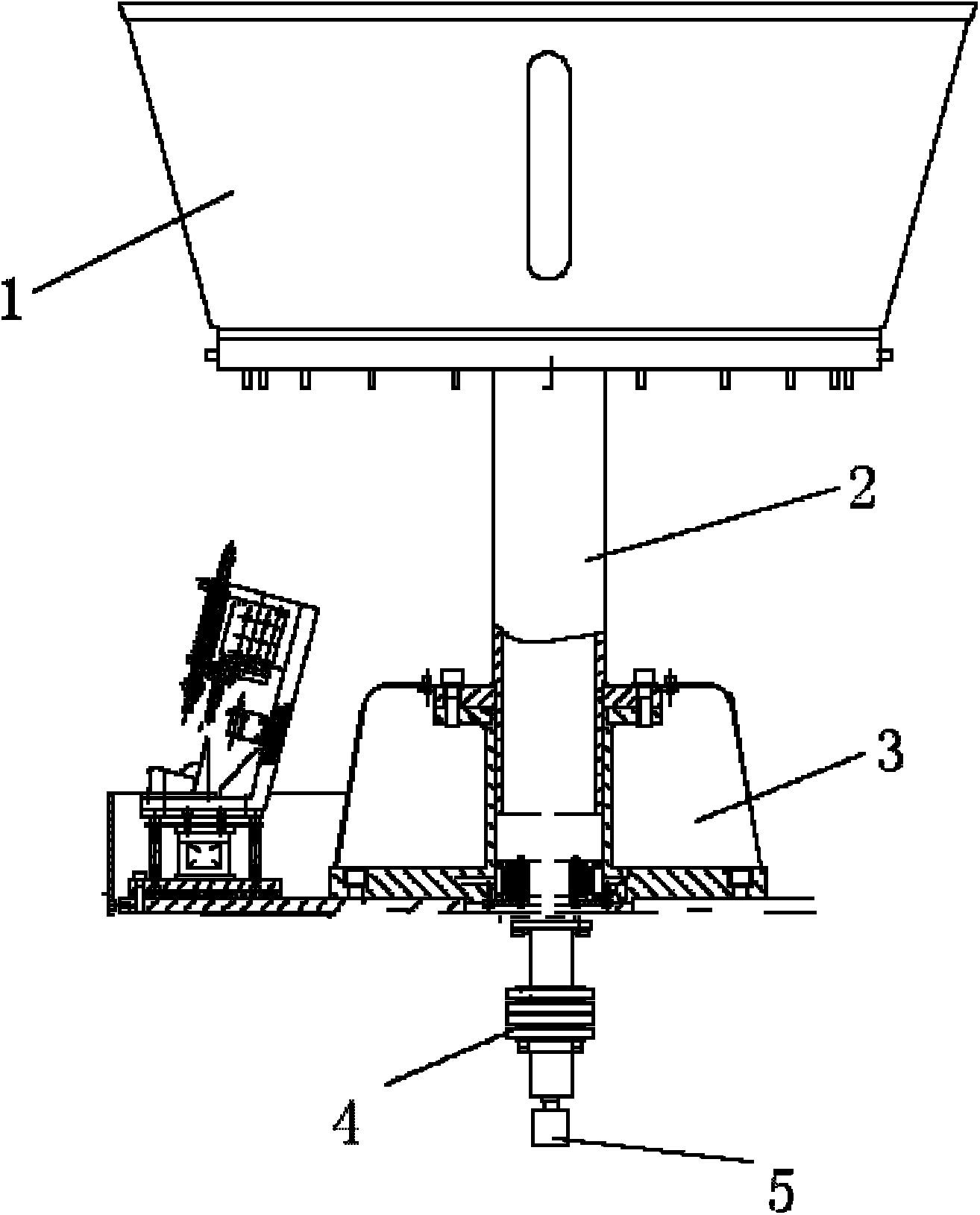
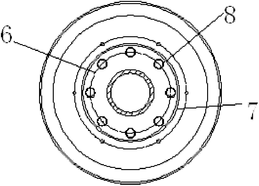
[0019] Such as figure 1 As shown, the present invention includes a sand filling bin body 1, a guide post 2, a main console 3, a collector slip ring 4, and a fixed shaft 5. The guide post 2 extends into the sand filling bin body 1, is fixedly connected with the sand filling bin body 1, and can rotate relative to the main operating table 3. Such as figure 2 As shown, the collector slip ring 4 is divided into two parts: the collector slip ring inner ring 6 and the collector slip ring outer ring 7. The collector slip ring inner ring 6 and the collector slip ring outer ring 7 are connected by an electromagnetic brush 8, and the collector slip ring Ring inner ring 6 and collector slip ring outer ring 7 can rotate relatively. The outer ring 7 of the collector slip ring is fixedly connected with the guide post 2, and the inner ring 6 of the collector slip ring is fixed on the main console 3 through the fixed shaft 5. The guide post 2 adopts a hollow structure, the power line penet...


PUM


Abstract

The invention relates to a power transmission mechanism used for a sand filling machine. The power transmission mechanism used for the sand filling machine comprises a sand filling storehouse and a main operation platform, wherein the sand filling storehouse can be rotatably connected with the main operation platform through a guide pillar, and the guide pillar is connected with a driving motor. The power transmission mechanism used for the sand filling machine further comprises a collector slip ring device, a power line and an air source line, wherein the power line and the air source line are respectively connected with external static electrical energy and an air source, penetrate through the guide pillar, enter into the collector slip ring device and are connected with a power source distribution device and an air resource device in a dynamic rotation mechanism, and the power transmission mechanism is enabled to achieve dynamic and static surface combination and power source feeding. Compared with the prior art, the power transmission mechanism used for the sand filling machine has the advantages that the rotation type sand filling is achieved, the volume of production is increased greatly, the efficiency is improved greatly and the like.

Description

technical field [0001] The invention relates to a power transmission mechanism, in particular to a dynamic and static surface combination to realize a power source feeding device. Background technique [0002] The traditional sand filling machine for pipe fittings can only achieve a single sand filling of the workpiece, which cannot guarantee the quality of the sand filling, and the phenomenon of waste is serious. The utility model patent with the patent number ZL200820032736.7 (applicant: Zhuang Tiancai, application date: 2008.02.28) discloses a sand filling vibration machine for pipe fittings. The sand filling vibration machine for pipe fittings consists of a frame, an The sand filling mechanism is composed of a positioning mechanism located in the middle of the frame and used to fix the pipe fittings, a vibration mechanism located in the lower part of the frame and used to drive the positioning mechanism to vibrate the pipe fittings. The sand filling mechanism has a disch...

Claims


Application Information

Patent Timeline
IPC IPC(8): B21D9/16
Inventor 程武山周玉凤刘汝斌高升高明
Owner SHANGHAI UNIV OF ENG SCI
Why Eureka
Try Eureka