
Spiral demoulding device of bevel gear injection mold

A technology of injection mold and demoulding device, which is applied in the field of demoulding and ejection mechanism, can solve the problems of high production cost, high maintenance cost and complex structure of injection molds, and achieve the effects of low cost, simplified structure and reliable operation

Active Publication Date: 2013-05-29
NINGBO SIMAI IND TECH
View PDF7 Cites 15 Cited by
  • Summary
  • Abstract
  • Description
  • Claims
  • Application Information

AI Technical Summary

Problems solved by technology

[0002] Injection-molded helical gear products require spiral ejection and demoulding. In the prior art, the oil cylinder is driven by the rack to drive the gear to rotate the screw to drive the product to carry out spiral ejection and demoulding. Due to the structure of the oil cylinder, rack, gear and screw linkage conversion mechanism The complexity is high and the cost is high, especially the production cost of an injection mold with more helical gear products in one mold, and because there are many motion conversion links and fault points, the maintenance cost of mold production and operation is high. Therefore, the existing technology has a structure Problems and deficiencies of complexity, many faults, and high cost

Method used


Image

  • Spiral demoulding device of bevel gear injection mold
  • Spiral demoulding device of bevel gear injection mold
  • Spiral demoulding device of bevel gear injection mold

Examples


Embodiment Construction

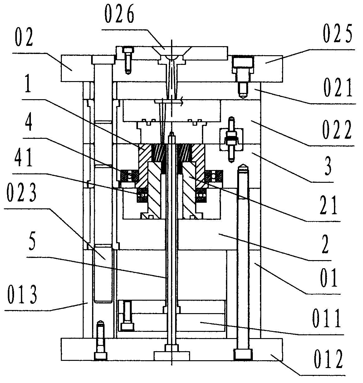
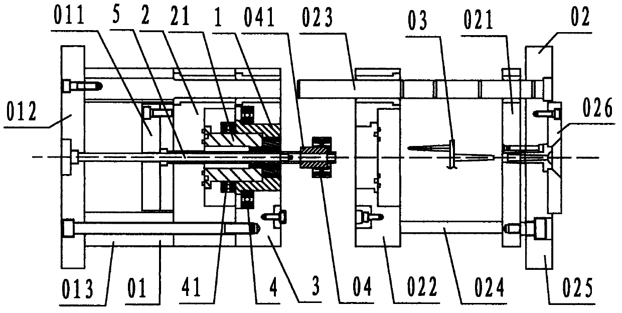
[0019] refer to Figure 1 ~ Figure 3 , a spiral demoulding device for a helical gear injection mold of the present invention, comprising a rotating cavity 1, a moving mold carrier plate 2, a pressing plate 3, an A bearing 4, a B bearing 41, and a sleeve 5, wherein: the rotating type Cavity 1 is a cylindrical step-shaped steel member with a flange on the bottom. The center of the rotary cavity 1 is provided with a circular stepped through hole with a small upper part and a larger lower part. The small stepped hole on the upper part of the rotary cavity 1 is called a helical tooth cavity. , the hole wall of the helical tooth cavity is provided with a profile for forming the cylindrical helical tooth of the helical gear product 04; the large stepped hole at the bottom of the rotary cavity 1 is called the bushing hole; the outer flange step of the rotary cavity 1 A bearing 4 is arranged on the upper surface, and the A bearing 4 is a radial ball bearing, and the inner ring of the A...


PUM


Abstract

The invention discloses a spiral demoulding device of a bevel gear injection mold. The spiral demoulding device of the bevel gear injection mold comprises a rotary mold cavity (1), a moving mold loading plate (2), a pressing plate (3), a bearing A (4), a bearing B (4) and an ejector sleeve (5). According to the spiral demoulding device, because the device formed by the components above is adopted, the side wall of the rotary mold cavity is provided a bevel gear molded surface which is used for forming a bevel gear product and is also named as bevel gear cavity; the rotary mold cavity can be rotatably arranged between the moving mold loading plate and the pressing plate through the bearing A and the bearing B; the upper part of a core rod of the ejector sleeve is used as a penetrating core for positioning a direct gear embedded element and is positioned in the center of the bevel gear cavity; the lower end of the sleeve core rod is fixedly connected with a base plate of the moving mold; the upper end of a sleeve of the ejector sleeve is positioned on the bottom of an embedded element hole below the bevel gear cavity; and the lower end of the sleeve part is fixedly connected with a top plate of the moving mold. Through the technical scheme that the rotary mold cavity is driven to rotate by the bevel gear product, one mould which can be used for producing multiple bevel gear injection molds by one mold can be simplified in structure, and reduces faults and the cost.

Description

technical field [0001] The invention relates to a demoulding and ejecting mechanism of an injection mold, in particular to a spiral demoulding device of a helical gear injection mold used for ejecting and demoulding an injection molded helical gear product. Background technique [0002] Injection-molded helical gear products require spiral ejection and demoulding. In the prior art, the oil cylinder is driven by the rack to drive the gear to rotate the screw to drive the product to carry out spiral ejection and demoulding. Due to the structure of the oil cylinder, rack, gear and screw linkage conversion mechanism The complexity is high and the cost is high, especially the production cost of an injection mold with more helical gear products in one mold, and because there are many motion conversion links and fault points, the maintenance cost of mold production and operation is high. Therefore, the existing technology has a structure Problems and deficiencies such as complexity...

Claims


Application Information

Patent Timeline
IPC IPC(8): B29C45/40
Inventor 钱景良严宇松王骏啸李建辉
Owner NINGBO SIMAI IND TECH
Features
  • Generate Ideas
  • Intellectual Property
  • Life Sciences
  • Materials
  • Tech Scout
  • Unparalleled Data Quality
  • Higher Quality Content
  • 60% Fewer Hallucinations
Learn More