Elastic clamping ring

A technology of elastic snap rings and snap rings, which is applied in the direction of connecting components, friction-clamped detachable fasteners, mechanical equipment, etc. Does not have other problems, to achieve the effects of not being prone to fatigue failure, improving elasticity, and good blocking effect

Active Publication Date: 2013-05-29
HANGZHOU BRANCH ZHEJIANG GEELY AUTOMOBILE RES INST +2
View PDF7 Cites 11 Cited by
  • Summary
  • Abstract
  • Description
  • Claims
  • Application Information

AI Technical Summary

Problems solved by technology

[0006] The first purpose of the present invention is to provide an elastic snap ring that can increase the elastic force of the snap ring and is not easy to fail under the condition of constant material consumption, so as to solve the problem that the existing elastic snap ring has small elastic force, prone to failure
[0007] The second object of the present invention is to provide an elastic snap ring that can be used as both an inner snap ring and an outer snap ring, so as to solve the problem that the existing elastic snap rings do not have universality
[0008] The third object of the present invention is to provide an elastic snap ring that is labor-saving in assembly and not easy to fall off, so as to solve the problem that the existing elastic snap ring does not have the advantages of labor-saving assembly and not easy to fall off

Method used


Image

  • Elastic clamping ring
  • Elastic clamping ring
  • Elastic clamping ring

Examples


Embodiment 1

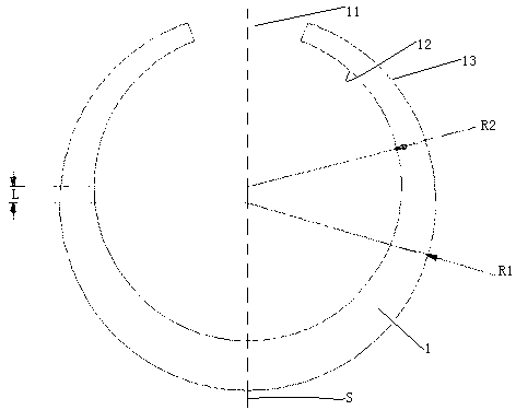
[0032] Embodiment one, see figure 1, an elastic snap ring, comprising an elastic snap ring body 1 . The clasp body 1 is provided with an opening 11 . The inner peripheral surface 12 of the clasp body is a rotating surface, and the rotating surface is a cylindrical surface. The outer peripheral surface 13 of the clasp body is a rotating surface, and the rotating surface is a cylindrical surface. The axis of the rotating body where the outer peripheral surface 13 of the snap ring body is located is parallel to the axis of the rotating body where the inner peripheral surface 12 of the snap ring body is located. The axis of the rotating body where the outer peripheral surface 13 of the snap ring body is located is located on the lower side of the axis of the rotating body where the inner peripheral surface 12 of the snap ring body is located. The opening 11 is located on the upper side of the axis of the rotating body where the inner peripheral surface 12 of the clasp body is l...

Embodiment 2

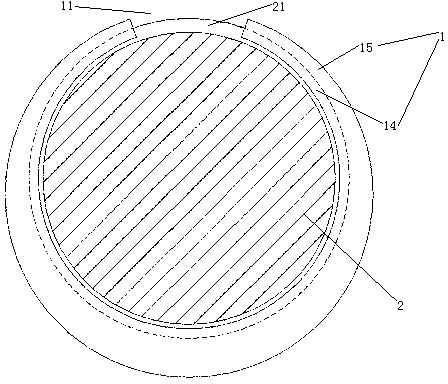
[0035] Embodiment two, see Figure 4 , the difference from the first embodiment is that: the axial end surface of the clasp body 1 is provided with a mounting groove 16 . The installation slot 16 is located on the blocking portion 15 . The mounting groove 16 is in the shape of an arc extending along the circumferential direction of the clasp body 1 . The mounting groove 16 extends to two sides of a plane S that equally divides the snap ring body along the circumferential direction. A reinforcement block 3 is provided in the installation groove 16 . The reinforcing block 3 is arc-shaped. It is a tight fit between the reinforcement block 3 and the installation groove 16 . Four booster hooks 31 are arranged on the axially outer end surface of the reinforcement block 3 . The distance between the axis of the rotating body where the outer peripheral surface of the snap ring body is located and the axis of the rotating body where the inner peripheral surface of the snap ring bod...

Embodiment 3

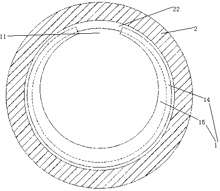
[0038] Embodiment three, see Image 6 , the difference from the second embodiment is: the right end of the installation groove 16 extends to the clamping portion 14 . Between the reinforcing block 3 and the mounting groove 16 is clearance fit, that is, the reinforcing block 3 is stuck in the mounting groove 16 and slides freely.

[0039] The method for installing and installing the present invention is:

[0040] see Image 6 , so that the snap ring body 1 is separated from the reinforcement block 3, first install the snap ring body 1 into the outer slot 21 of the object 2 provided with the slot, and then assemble the reinforcement block 3 into the installation slot 16 at the stopper 15 in the above part;

[0041] see Figure 7 , and then make the reinforcement block 3 slide toward the right end of the installation groove in the installation groove 16, so that the right end of the reinforcement block 3 enters the part of the installation groove 16 located on the clamping pa...


PUM


Abstract

The invention relates to clamping rings. An elastic clamping ring comprises an elastic clamping ring body, an opening is arranged in the clamping ring body, the inner circumferential face of the clamping ring body and the outer circumferential face of the clamping ring body are both spiral faces, and a rotator shaft at which the outer circumferential face the clamping ring is arranged and the opening are arranged at two sides of a shaft of the rotator in which the inner circumferential face of the clamping ring is arranged. The elastic clamping ring is capable of enabling elastic force of the elastic clamping ring to be increased and not prone to being out of operations to solve the problems that an elastic clamping ring in the prior art is small in elastic force and prone to being out of operations.

Description

technical field [0001] The invention relates to a snap ring, in particular to an elastic snap ring. Background technique [0002] There are two types of snap rings in terms of installation methods, one is a split type snap ring that fixes the snap ring body in the snap groove through an external connection structure, and the other is fixed in the snap ring through the snap ring body's own elasticity. The elastic snap ring (also known as the snap ring). [0003] A split-type clasp is disclosed in a patent document whose Chinese patent number is 2010203026617, the date of authorization announcement is October 6, 1010, and the name is "roll clasp". The split snap ring has the advantages of reliable connection when it is connected in the card slot, but has the following disadvantages: poor structure compactness, and can only be used as an outer snap ring instead of an inner snap ring. [0004] In order to overcome the above-mentioned shortcomings of the split snap ring, an...

Claims


Application Information

Patent Timeline
Patent Type & Authority Applications(China)
IPC IPC(8): F16B2/22
Inventor 吴飞阳陈勇罗大国方少权沈吉赵福全
Owner HANGZHOU BRANCH ZHEJIANG GEELY AUTOMOBILE RES INST
Why Eureka
Try Eureka