Light-emitting diode (LED) light source
An LED light source and reflector technology, applied in the field of LED lighting, can solve the problems of low utilization rate of lighting luminous flux and unreasonable light distribution form, and achieve the effect of improving the utilization rate of lighting luminous flux and reducing light waste.
- Summary
- Abstract
- Description
- Claims
- Application Information
AI Technical Summary
Problems solved by technology
Method used
Image


Examples
Embodiment 1
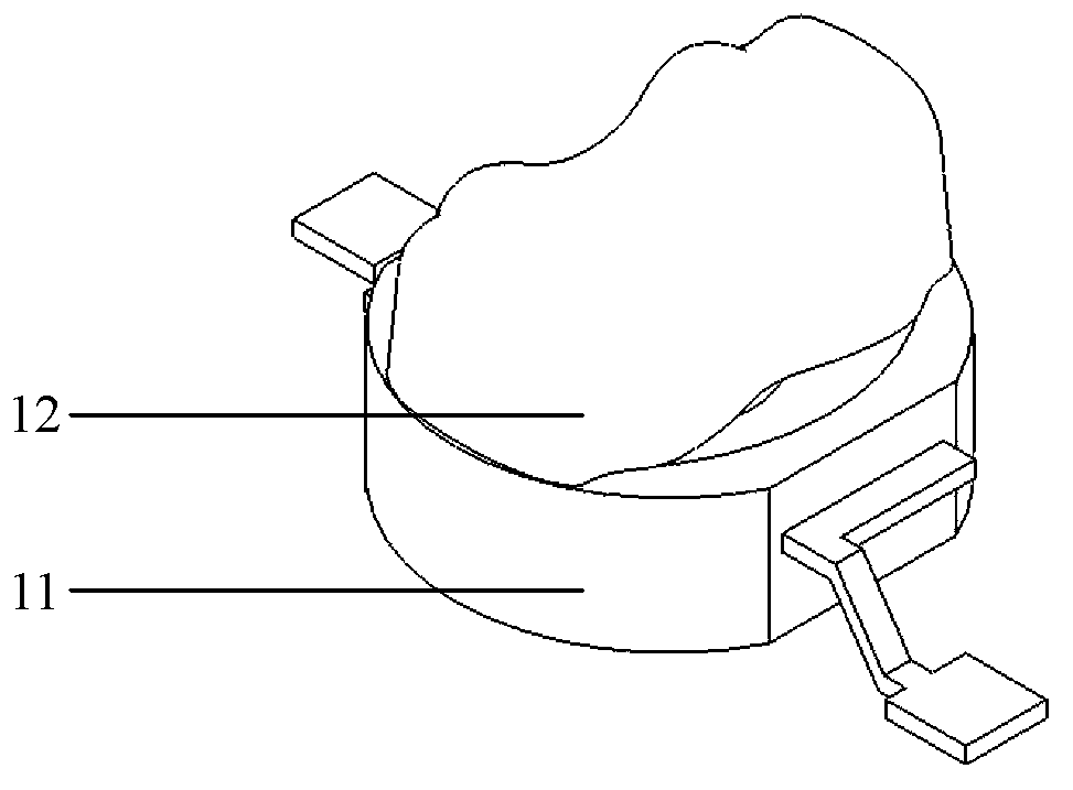
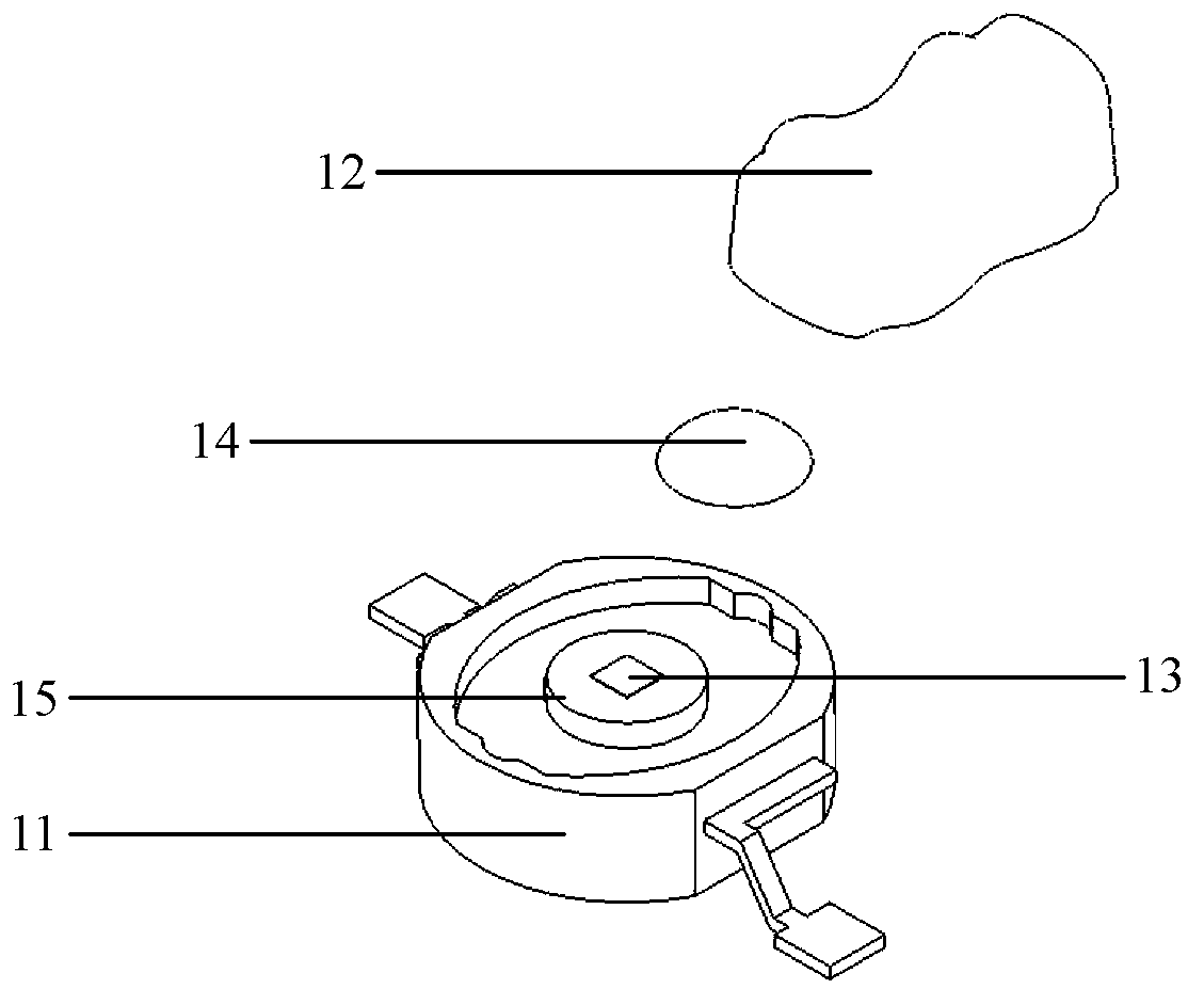
[0083] refer to figure 1 , figure 2 , image 3 , figure 1 It is a schematic structural diagram of the LED illuminant provided in Embodiments 1, 2, and 6 of the present invention, figure 2 It is a schematic diagram of the structural decomposition of the LED illuminant provided by Embodiments 1, 2, and 6 of the present invention, image 3 It is the front view of the LED illuminant provided by Embodiments 1, 2 and 6 of the present invention. It can be seen from the figure that the LED illuminant 1 is an LED single lamp with a multi-peak lens 12 through a light distribution process, and is composed of a packaging bracket 11 , a multi-peak lens 12 , a light-emitting chip 13 and a fluorescent glue 14 . The center of the packaging bracket 11 is a cylindrical base 15, the light-emitting chip 13 is located at the center of the upper surface of the cylindrical base 15, and the fluorescent glue 14 is coated on the upper surface of the cylindrical base 15 and wraps the light-emittin...
Embodiment 2
[0088] refer to Figure 9 , Figure 10 , Figure 9 It is a schematic structural diagram of the LED light source provided in Embodiment 2 of the present invention, Figure 10 It is a schematic exploded view of the structure of the LED light source provided by Embodiment 2 of the present invention; it can be seen from the figure that the LED light source provided by Embodiment 2 of the present invention includes: LED illuminant 1, reflector 2, reflector substrate 21; The closed cavity of the side wall of the device 2 surrounds the LED illuminant 1. There is an opening at the bottom of the reflector substrate 21 and cooperates with the packaging bracket 11. The center of the opening at the bottom of the reflector substrate 21 coincides with the center of the bottom surface of the packaging bracket 11; the multi-peak lens The C0-180 section 3 of 12 coincides with the C0-180 section 3 of the reflector 2, and the C90-270 section 4 of the multi-peak lens 12 coincides with the C90-2...
Embodiment 3
[0091] refer to Figure 14 , Figure 15 , Figure 16 , Figure 14 It is a schematic structural diagram of the LED illuminant provided by Embodiment 3 of the present invention, Figure 15 It is a schematic diagram of an exploded structure of the LED illuminant provided by Embodiment 3 of the present invention, Figure 16 It is a front view of the LED illuminant provided by Embodiment 3 of the present invention. It can be seen from the figure that the LED illuminant 1 is an LED single lamp with a multi-peak lens 12 through a light distribution process, and is composed of a package base 16, a multi-peak lens 12, a light-emitting chip 13, and a phosphor 17; The light-emitting chip 13 is located in the center of the upper surface of the packaging substrate 16, and the phosphor powder 17 is attached to the upper surface of the packaging substrate 16 and wraps the light-emitting chip 13; from the front view, the top of the outline of the multi-peak lens 12 presents multiple extre...
PUM
 Abstract
Description
Claims
Application Information
 - R&D
- Intellectual Property
- Life Sciences
- Materials
- Tech Scout
- Unparalleled Data Quality
- Higher Quality Content
- 60% Fewer Hallucinations
Browse by: Latest US Patents, China's latest patents, Technical Efficacy Thesaurus, Application Domain, Technology Topic, Popular Technical Reports.
© 2025 PatSnap. All rights reserved.Legal|Privacy policy|Modern Slavery Act Transparency Statement|Sitemap|About US| Contact US: help@patsnap.com