Non-contact temperature measuring method

A technology of temperature measurement and brightness, applied in the field of non-contact temperature measurement, it can solve the problems of small temperature range, unusable, poor practicability, etc.

Active Publication Date: 2013-05-29
IND TECH RES INST
View PDF3 Cites 9 Cited by
  • Summary
  • Abstract
  • Description
  • Claims
  • Application Information

AI Technical Summary

Problems solved by technology

When the temperature of the second wavelength G is lower than 1253K, the brightness tends to be 0

Method used


Image

  • Non-contact temperature measuring method
  • Non-contact temperature measuring method
  • Non-contact temperature measuring method

Examples


Embodiment Construction

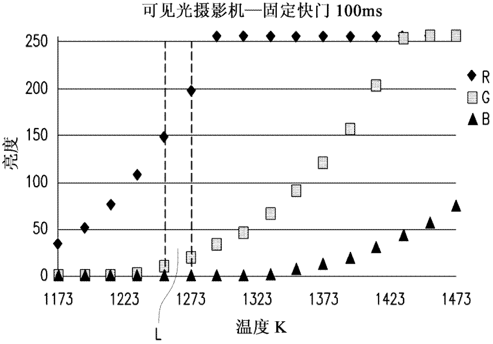
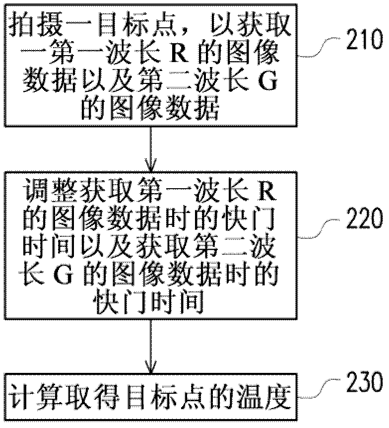
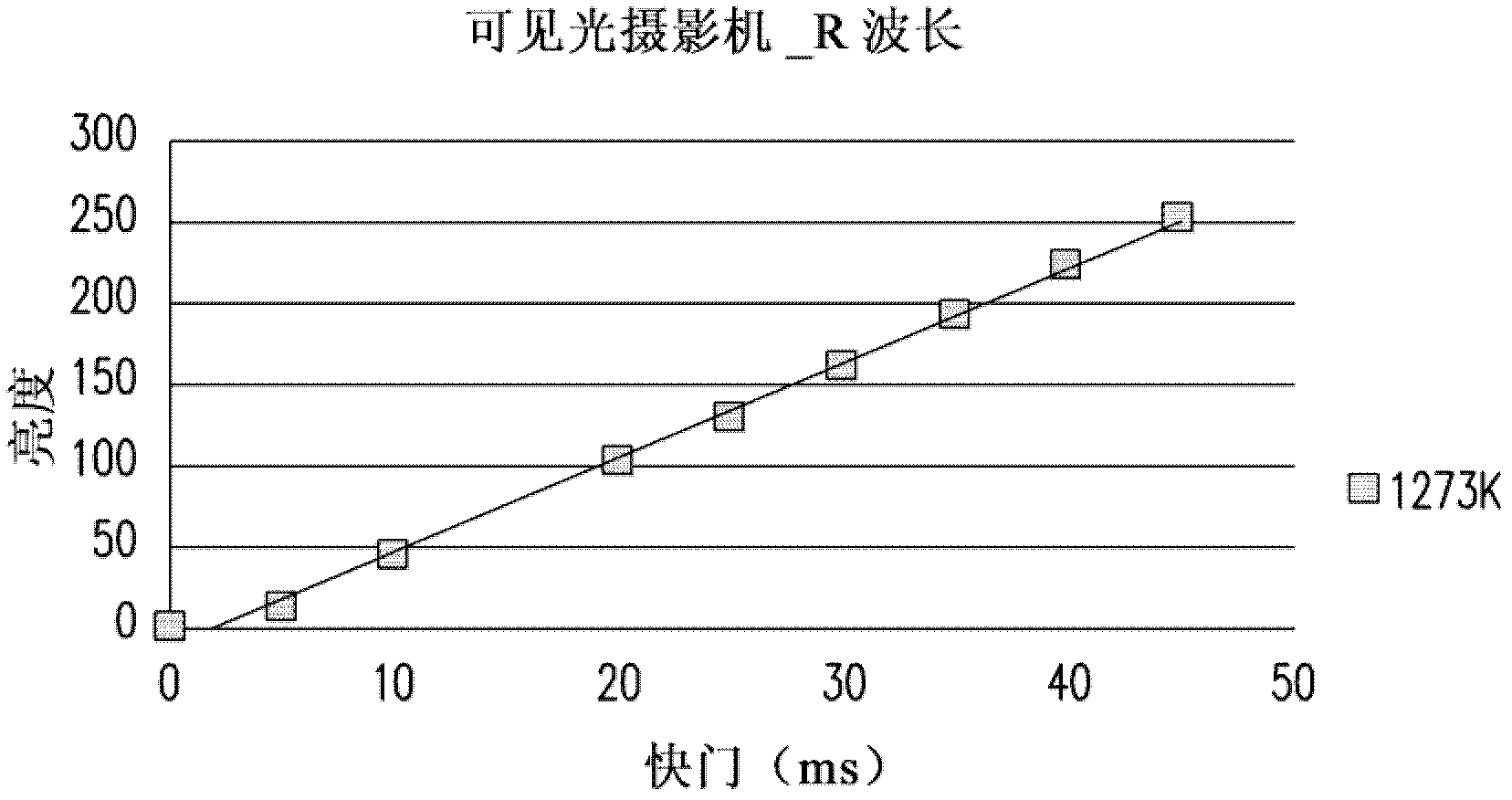
[0026] figure 2 It is a flowchart of a temperature measurement method according to an embodiment of the present invention. In this embodiment, the main process includes a step 210 of photographing a target point to obtain image data of a first wavelength R and image data of a second wavelength G. When shooting the target point, step 220 is also executed to adjust the shutter time when acquiring the image data of the first wavelength R and the shutter time when acquiring the image data of the second wavelength G, so as to obtain a first wavelength R corresponding to A brightness and a second brightness corresponding to the second wavelength G. Finally, in step 230 , the temperature of the target point is obtained through calculation.

[0027] In an embodiment of the present invention, the step of adjusting the shutter time when acquiring the image data of the first wavelength R and the shutter time when acquiring the image data of the second wavelength G is carried out by i...


PUM


Abstract

A non-contact temperature measuring method comprises the steps of shooting a target point to obtain the image data of a first wavelength and the image data of a second wavelength; when the target point is shot, adjusting the shutter time for obtaining the image data of the first wavelength and the shutter time for obtaining the image data of the second wavelength to obtain a first brightness corresponding to the first wavelength and a second brightness corresponding to the second wavelength; and computing the temperature of the target point according to the following formula (1), wherein lambda 1 is the first wavelength, lambda 2 is the second wavelength, L lambda 1 (T) is the first brightness, L lambda 2 (T) is the second brightness, A is a correction coefficient, S1 is the shutter time for obtaining the image data of the first wavelength, and S2 is the shutter time for obtaining the image data of the second wavelength. In the formula: constant C=hc /k, k is a Planck constant, c is light velocity, and h is a Boltzmann constant.

Description

technical field [0001] The present invention relates to a temperature measurement method, and in particular to a non-contact temperature measurement method suitable for measuring the temperature field of a combustion furnace. Background technique [0002] Industrial combustion systems, such as industrial steelmaking furnaces, thermal power plants and combustion furnaces. During the combustion process, it is often necessary to monitor the temperature distribution in the furnace of the combustion field, such as the temperature of the furnace wall and the temperature of the steel billet. The purpose of measuring the temperature of the furnace wall is to avoid damage to the structure of the furnace body due to excessive furnace wall temperature, resulting in danger; and measuring the temperature of the billet can pre-judge the product quality, and then change the operation setting to improve the product yield. [0003] The combustion field temperature measurement device is divi...

Claims


Application Information

Patent Timeline
IPC IPC(8): G01J5/00
Inventor 陈佳鸿郑仪诚黄立方徐振凯
Owner IND TECH RES INST
Why Eureka
Try Eureka