
Computer-aided design (CAD) graphical modeling method for software/hardware system

A graphical modeling, software and hardware technology, applied in special data processing applications, instruments, electrical digital data processing, etc., can solve the problem of not being able to easily modify the software and hardware task association scheme, unable to realize effective division of labor in software and hardware development, and lack of task association Matching with communication paths and other issues, to achieve the effect of shortening the system modeling cycle, intuitive and efficient modeling features, and reducing development risks

Active Publication Date: 2013-05-29
TSINGHUA UNIV
View PDF4 Cites 9 Cited by
  • Summary
  • Abstract
  • Description
  • Claims
  • Application Information

AI Technical Summary

Problems solved by technology

[0004] In traditional CAD tools, the interfaces and attributes of software and hardware modules are defined by users themselves, lacking a unified interface and package definition for modules, which is not conducive to the management and reuse of modules; when the system scale is large and the structure is complex, the graphical model It is very complicated and difficult to grasp and manage clearly; there is no effective task correlation and communication path matching between the separately established software models and hardware models, so that developers still need to deal with complex software-hardware coupling problems when implementing the system, and it is impossible to realize software-hardware Effective division of labor for development, and the software and hardware task association scheme cannot be easily modified
The system development process of software and hardware modeling based on traditional CAD tools still faces great difficulties

Method used


Image

  • Computer-aided design (CAD) graphical modeling method for software/hardware system
  • Computer-aided design (CAD) graphical modeling method for software/hardware system
  • Computer-aided design (CAD) graphical modeling method for software/hardware system

Examples


Embodiment Construction

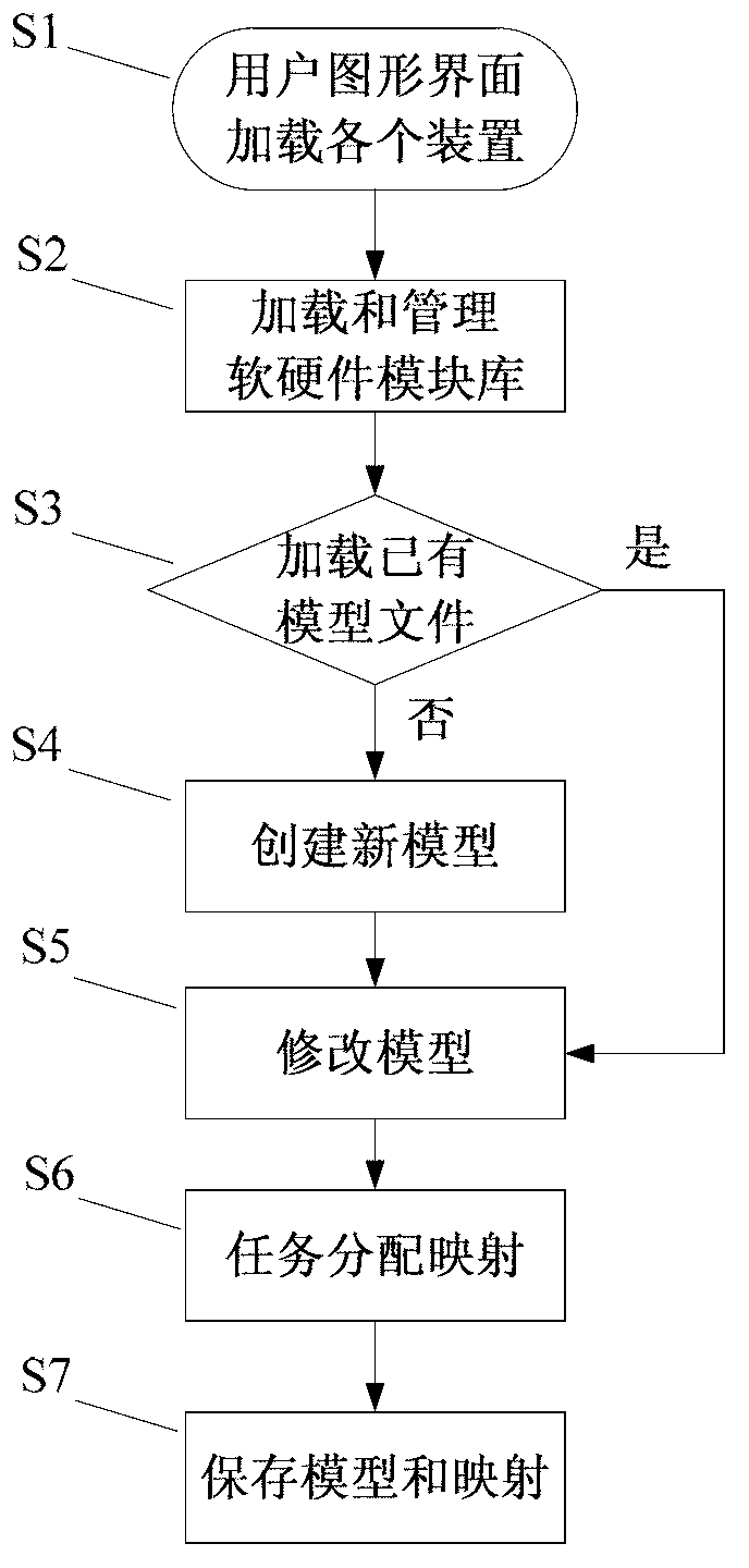
[0061] A method for graphically modeling software and hardware systems, including the following steps:

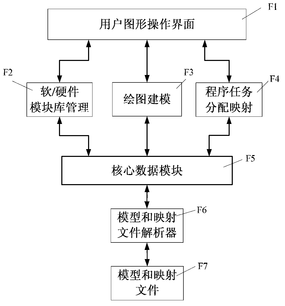
[0062] a) User graphical operation interface loads software / hardware module library management device, drawing modeling device, program task allocation mapping device, and model and mapping file parser;

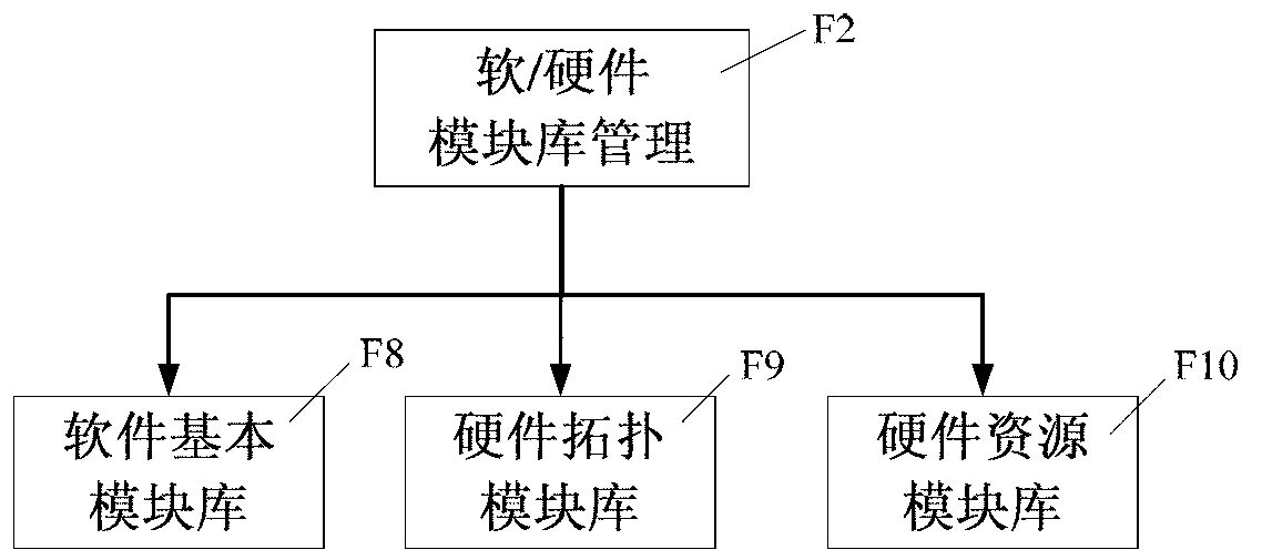
[0063] b) The software / hardware module library management device loads the existing software and hardware module library and performs library management;

[0064] c) The model and mapping file parser parses and loads the existing software and hardware models, otherwise the drawing modeling device creates a new software and hardware model;

[0065] d) The drawing modeling device modifies the loaded or created software and hardware models;

[0066] e) The program task allocation mapping device associates the software and hardware models, and specifies the software to hardware task allocation mapping plan;

[0067] The model and mapping file parser saves software and hardware models and...


PUM


Abstract

The invention discloses a computer-aided design (CAD) graphical modeling method for a software / hardware system and belongs to the field of graphical modeling. The method is characterized by comprising a user graph manipulation interface F1, a software / hardware module library management device F2, a graphics modeling device F3, a program task allocation mapping device F4, a core data module F5, a model and mapping file resolver F6 and a model and mapping file F7. The user graph manipulation interface F1 is used for completing the function of modeling according to instructions such as the drawing instruction of a user; the software / hardware module library management device F2 is used for managing a software / hardware basic module with parameters capable of being configured; the graphics modeling device F3 is used for building a software / hardware graphical model by use of the software / hardware basic module; the program task allocation mapping device F4 is used for building a task allocation mapping relationship from software to hardware; the core data module F5 is used for defining various data contents of a modeling system; the model and mapping file resolver F6 is used for resolving files stored according to formats to acquire the various data contents, or storing the data contents as the files according to the formats; and the model and mapping file F7 is used for storing the files according to the formats. By means of the CAD graphical modeling method for the software / hardware system, visualized and efficient software / hardware integrated modeling can be achieved by the user, and an allocation mapping scheme of software tasks on the hardware can be specified.

Description

Technical field [0001] The invention belongs to the field of comprehensive modeling of software and hardware system development, and specifically is a device for graphically modeling software and hardware systems and establishing a mapping relationship between software and hardware tasks. Background technique [0002] In the development of system software / hardware, the traditional program development method of writing line-by-line code for software tasks is inefficient and has poor versatility. The tight coupling of software and hardware development puts higher requirements on the level of developers, and the developed system It has the shortcomings of unclear model structure, high complexity and difficult to maintain. [0003] Before implementing the system, first use software and hardware graphical modeling tools to establish a system model. System development based on a clear structure model can partially solve the above problems. Commonly used graphical modeling tools are CAD ...

Claims


Application Information

Patent Timeline
Patent Type & Authority Applications(China)
IPC IPC(8): G06F17/50
Inventor 汤俊汤小为罗军韦文鉴福生李宁
Owner TSINGHUA UNIV
Learn More