
Multi-balloon dilation device for placing catheter tubes

An expansion device and balloon technology, applied in the direction of catheters, dilators, balloon catheters, etc.

Active Publication Date: 2013-05-29
AVENT INC
View PDF5 Cites 7 Cited by
  • Summary
  • Abstract
  • Description
  • Claims
  • Application Information

AI Technical Summary

Problems solved by technology

[0010] In response to the difficulties and problems discussed herein, the present invention provides expansion devices and expansion systems

Method used


Image

  • Multi-balloon dilation device for placing catheter tubes
  • Multi-balloon dilation device for placing catheter tubes
  • Multi-balloon dilation device for placing catheter tubes

Examples


Embodiment Construction

[0025] Reference will now be made in detail to one or more embodiments, examples of which are illustrated in the accompanying drawings. It should be appreciated that features illustrated or described as part of one embodiment can be used with another embodiment to yield a still further embodiment.

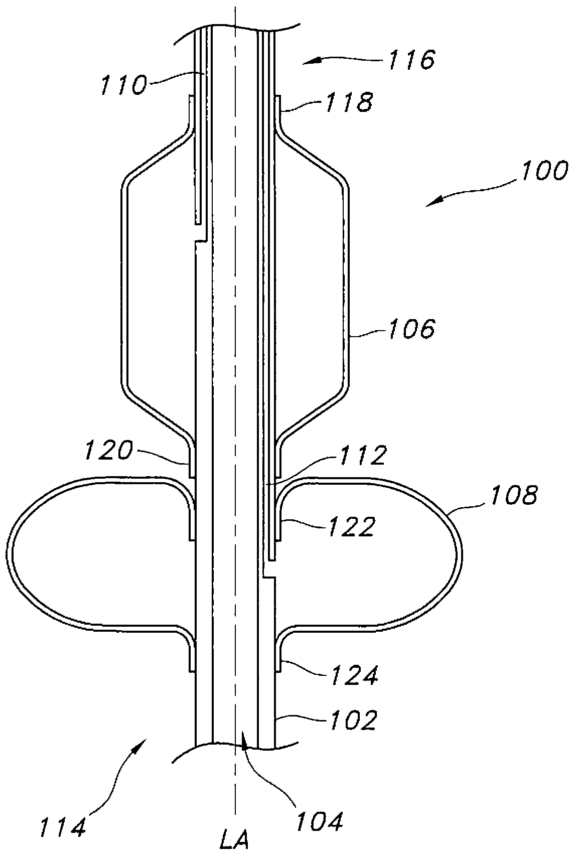
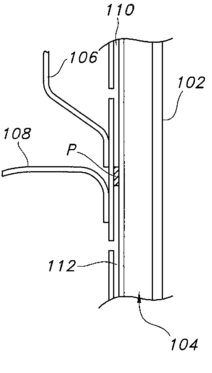
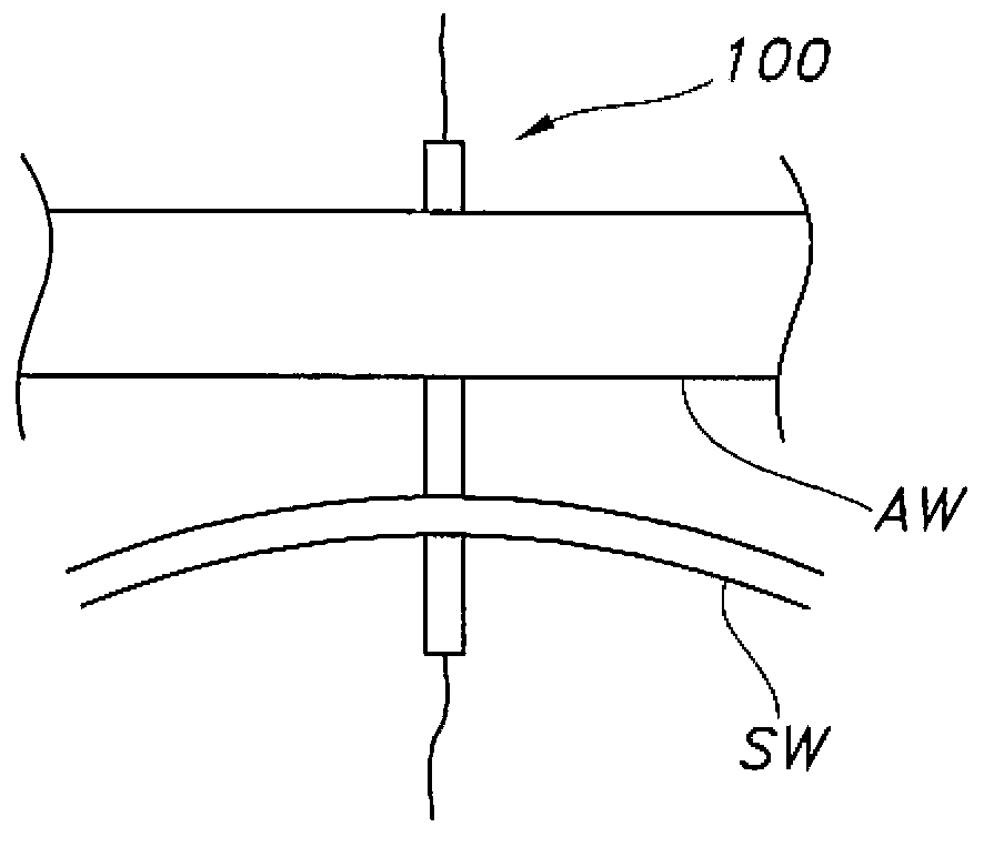
[0026] Referring now to the accompanying drawings, the figure 1 An exemplary ostium dilation device 100 is shown in side cross-sectional view in FIG. 2 , and includes a tubular support 102 that defines at least one continuous channel 104 through the device. The continuous channel is configured to accommodate the guide wire.

[0027] Tubular support 102 has a length, a width and a longitudinal axis "LA". The tubular support 102 should be flexible but not so flexible that it tends to fold or kink when pressure is applied radially or axially, and the width of the tubular support should be small enough to fit within the working channel of the endoscope. For example, the tubular supp...


PUM


Abstract

A stoma dilation device that includes a tubular support defining a continuous pathway through the device; at least one inflatable dilation balloon and at least one inflatable retention balloon located on the tubular support; and inflation lumens for each balloon. The inflatable dilation balloon forms at least a first portion of the device and the inflatable retention balloon forms at least a second portion of the device. The inflatable retention balloon is configured to have a diameter upon full, unrestrained inflation that is greater than the largest diameter of the inflatable dilation balloon upon inflation.

Description

technical field [0001] The present invention relates to catheters such as feeding tubes and their placement in a patient. Background technique [0002] There are many situations that require the insertion of catheters in body cavities to achieve desired medical goals. A relatively common situation is to provide nutritional solutions or drugs directly into the stomach or intestines. An opening is made in the stomach or intestinal wall and a catheter is placed through the opening. This surgical opening and / or the procedure to create the opening is commonly referred to as "gastrostomy". A feeding solution can be infused through a catheter to provide nutrition directly to the stomach or intestines (called enteral feeding). A variety of different catheters for enteral feeding have been developed over the years, including some that are "low profile" relative to the portion of the catheter that rests on the patient's skin, as well as those that have more traditional or non-low p...

Claims


Application Information

Patent Timeline
Patent Type & Authority Applications(China)
IPC IPC(8): A61B17/34A61J15/00
CPCA61B17/3415A61M2205/0227A61M25/1002A61J15/0015A61M29/02A61B2019/4836A61J15/00A61M25/01A61M39/08A61J15/0042A61J15/0038A61M25/1011A61M2025/1013A61B17/29A61M13/003A61M25/09
Inventor K-M·泰D·J·麦克迈克尔J·A·罗特拉N·C·格里菲斯E·A·赖卡特C·E·罗伊S·A·霍利E·B·梅森
Owner AVENT INC
Learn More