Centrifugal pump

A technology for centrifugal pumps and pump shafts, applied to pumps, drive pumps, non-variable pumps, etc., can solve problems such as complex structures and pump stability, and achieve reduced slurry loss and no slurry loss Effect

Active Publication Date: 2013-05-29
ANDRITZ AG
View PDF6 Cites 12 Cited by
  • Summary
  • Abstract
  • Description
  • Claims
  • Application Information

AI Technical Summary

Problems solved by technology

These known systems require a very complex construction and likewise require considerable effort to set up the control loop which has to be tuned for different types of slurry from different plants
Additionally, existing systems are not reliable enough to completely prevent fiber loss
In addition to loss of stock, fiber loss can lead to problems with pump stability

Method used


Image

  • Centrifugal pump
  • Centrifugal pump
  • Centrifugal pump

Examples


Embodiment Construction

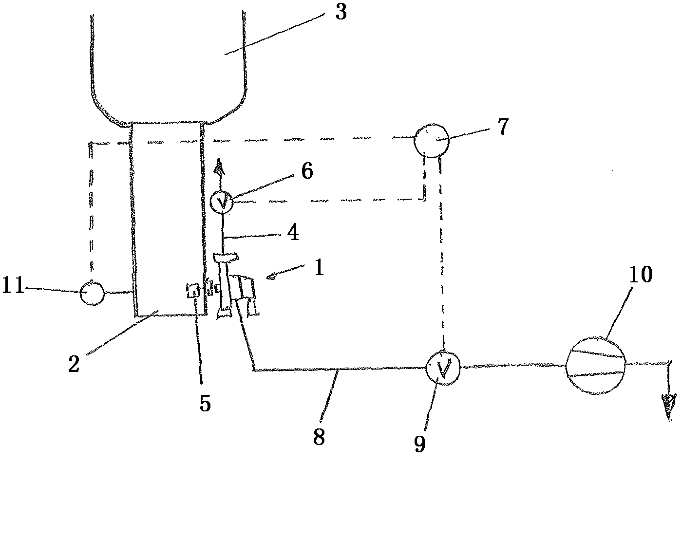
[0013] figure 1 Shown is a system for conveying a gas-containing suspension with a prior art degassing device. Here, the centrifugal pump 1 is installed in a lower side portion of a standpipe 2 arranged below a large liquid storage tank 3 such as a bleaching tower or the like. The pump 1 has a discharge pipe 4 for the medium to be pumped, for example a fiber stock suspension, and at the inlet there is a rotor 5 which is located integrally inside the standpipe 2 and is integrated with the wall of the standpipe 2 in the The combined rotor 5 is intended to generate turbulent flow for fluidizing the fiber stock suspension. In the outlet pipe 4 there is a regulating valve 6 which is connected to a control unit 7 .

[0014] Furthermore, the pump 1 has an exhaust pipe 8 in which a regulating valve 9 and a vacuum pump 10 are installed. The control unit 7 controls the fluid in the outlet pipe 4 by means of the control valve 6 and in particular by means of the control valve 9 in the ...


PUM


Abstract

The invention relates to a centrifugal pump for delivering a gaseous suspension, in particular a fibrous stock suspension, having a pump impeller (12) which has at least one opening (15) in the base plate and ribs (16) on its rear side, wherein a separator unit (17) is provided, consisting of a separator housing (25) with a stationary disc (18) and a disc (22) which rotates together with the pump shaft (21), wherein the separator unit (17) is arranged in the pump housing, as viewed in the axial direction onto the pump impeller (12), so as to adjoin the pump impeller (12) on the rear side of the latter, and wherein the separator housing (25) has a gas collecting chamber (31) with gas discharge line (28). It is characterized in that the disc (22) which rotates together with the pump shaft (21) has a closed surface (23) without openings. As a result, the stock loss can be reduced and improved pump stability of the centrifugal pump can be achieved during the delivery of a gaseous suspension, in particular a fibrous stock suspension.

Description

technical field [0001] The invention relates to a centrifugal pump for conveying gas-containing fiber stock suspensions, the centrifugal pump having a pump impeller with at least one opening in the base plate and ribs on the rear side, in which a A separator unit consisting of a separator housing with a fixed disc and a disc that rotates with the pump shaft, in a centrifugal pump when the pump impeller is viewed in the axial direction, the separator unit is arranged In the pump housing and adjoining the pump impeller on the rear side thereof, and in centrifugal pumps, the separator housing has a plenum with an exhaust pipe. Background technique [0002] Today, when operating pumps to pump media compatible fibrous stock suspensions, the air must be separated from the stock in order to ensure that the stock can be pumped. This is accomplished by first liquefying the slurry by applying shear (either by means of a "liquefier or fluidizer" mounted on the pump shaft or by an exte...

Claims


Application Information

Patent Timeline
Patent Type & Authority Applications(China)
IPC IPC(8): F04D9/00
CPCF04D9/003F04D7/045
Inventor 路德维希·米卡尔
Owner ANDRITZ AG
Why Eureka
Try Eureka