Portable working machine

A kind of operation machinery and portable technology, applied in agricultural machinery and tools, machinery equipment, agriculture, etc., can solve the problems of easy shaking of poles, troublesome loading and unloading of connecting structural parts, and fixing of poles that cannot be separated, so as to achieve the goal of not being easy to loosen open effect

Active Publication Date: 2013-06-05
MAKITA CORP
View PDF8 Cites 8 Cited by
  • Summary
  • Abstract
  • Description
  • Claims
  • Application Information

AI Technical Summary

Problems solved by technology

[0005] When the rods are connected using pins, the separated rods cannot be reliably fixed to each other because there is a gap around the pin, etc.
As a result, for example, when carrying out work with the pole on the power source side divided into two (parts), the pole on the working part side tends to vibrate
[0006] In the case where the rods are connected using a connecting member, although the separated rods can be securely fixed to each other, the connecting work requires an additional tool.
Since it is necessary to prepare tools for the work, it is troublesome to attach and detach the connecting members

Method used


Image

  • Portable working machine
  • Portable working machine
  • Portable working machine

Examples


Embodiment Construction

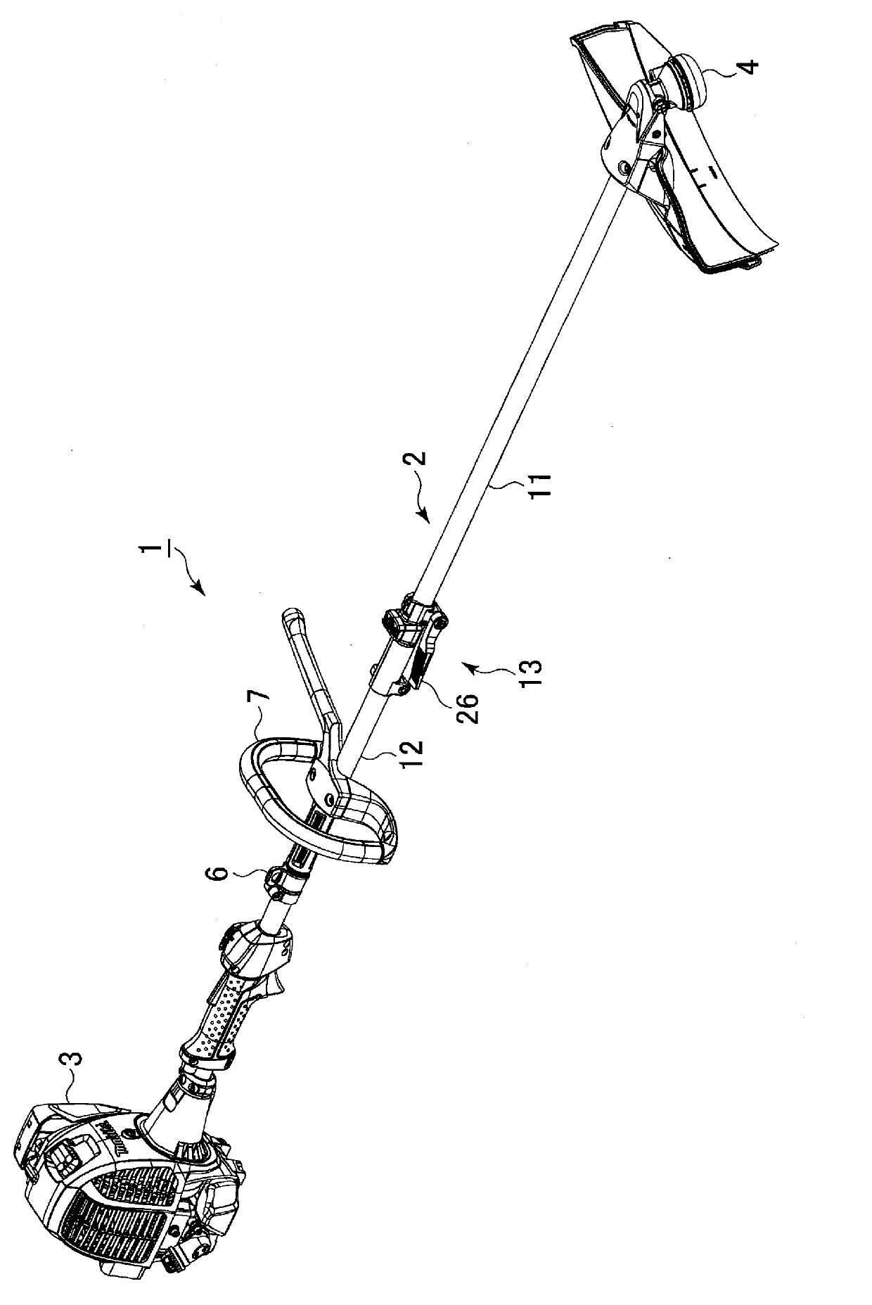
[0030] figure 1 It is a perspective view of the brush cutter 1 which concerns on embodiment of this invention.

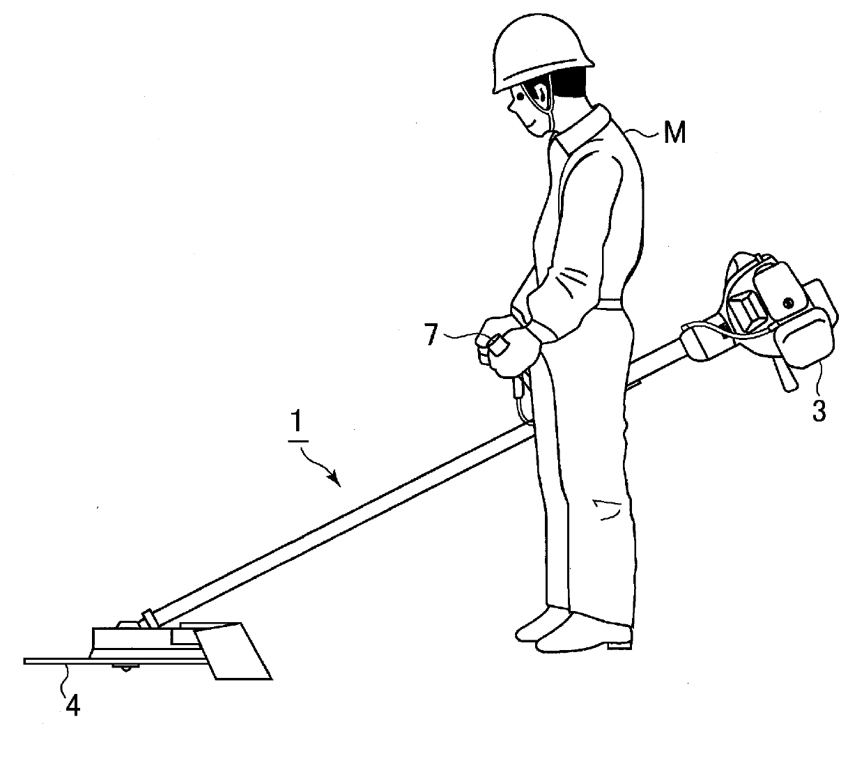
[0031] The brush cutter 1 is a type of portable work machine that is carried and used by an operator M. As shown in FIG.

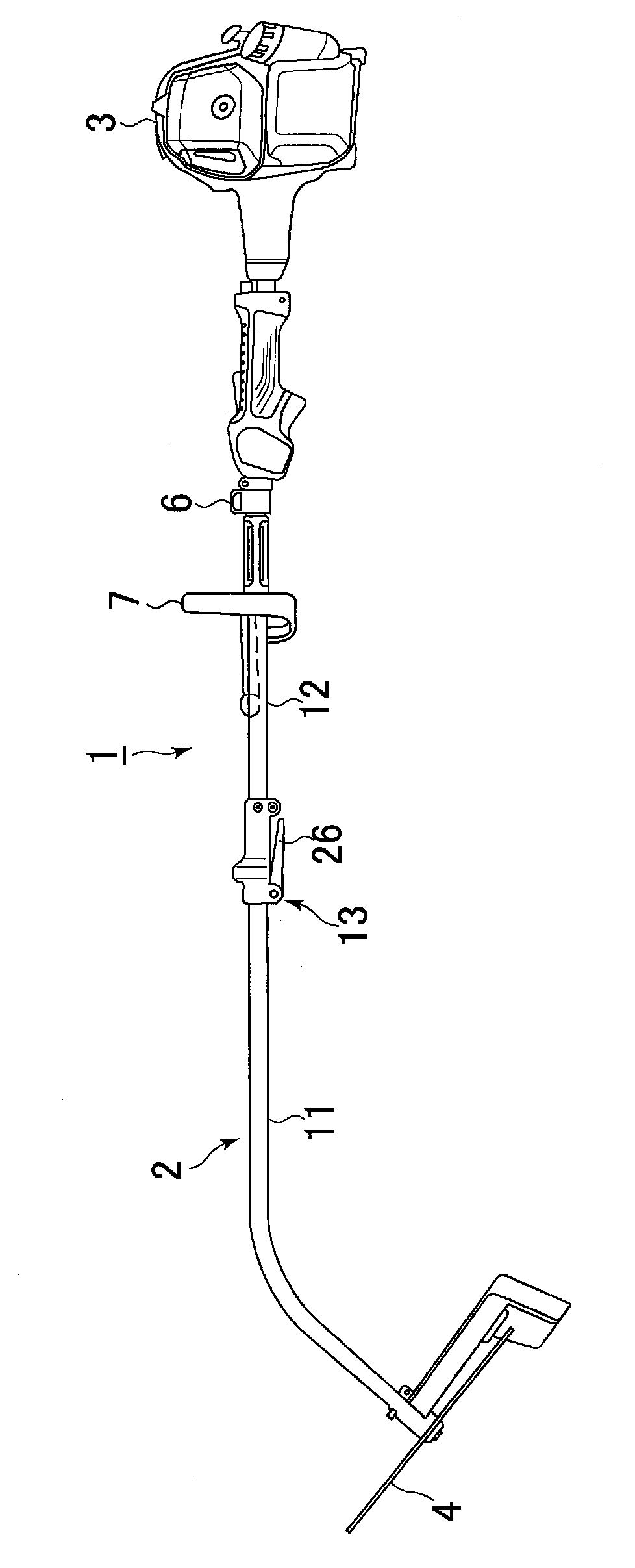
[0032] The brush cutter 1 has an operating lever 2 formed from a long tube.

[0033] An engine 3 is provided at one end of the operating rod 2 . Instead of the engine 3, a drive motor operated by electric power from a storage battery may be used as a power source.

[0034] A tool 4 is mounted on the other end of the operating rod 2 . The work tool 4 is driven by a power source such as an engine 3 . In addition, the tool 4 is connected to the engine 3 by a transmission shaft built in the operating lever 2 , and the tool 4 is driven by the driving force of the engine 3 .

[0035] In addition, a hanger 6 , a handle 7 and the like are installed on the operating lever 2 .

[0036] figure 2 yes figure 1 An explanatory diagram of a usage state...


PUM


Abstract

The present invention provides a portable working machine to solve the problems occurs when a control rod of the conventional portable working machine forms a split structure. A power source (3) is arranged on one end of the control rod (2) of the portable working machine (1), a working portion (4) is arranged on the other end of the control rod (2), and the control rod (2) can be split into two rods. The split rods (11, 12) are fixedly connected to each other by tightening a fasten part (24) of a joint part (13) using a lever (26), the fasten part (24) is combined with the lever (26), and the lever (26) is located at a position along with the control rod (2) when the fasten part (24) is tightened with the lever (26).

Description

technical field [0001] The present invention relates to a portable working machine in which a power source is provided at one end of an operating rod, a working portion is provided at the other end of the operating rod, and the operating rod can be divided into two or more rods along the length direction. Background technique [0002] Among portable working machines such as brush cutters, there is known a portable working machine in which an operating lever can be divided into two or more levers in the longitudinal direction (for example, Patent Document 1). [0003] Patent Document 1: Japanese Authorized Utility Model No. 3123389 [0004] However, conventionally separated rods are connected by a pin or a connecting member as shown in Patent Document 1. [0005] When the rods are connected using pins, the separated rods cannot be securely fixed to each other because there is a gap or the like around the pins. As a result, for example, when carrying out work with the pole o...

Claims


Application Information

Patent Timeline
Patent Type & Authority Applications(China)
IPC IPC(8): A01D34/63A01D34/835
CPCA01G3/062A01D34/902F16B7/1418A01G3/067Y10T403/32467
Inventor 鹫见卓也渡边耕次小岛真也
Owner MAKITA CORP
Why Eureka
Try Eureka