Gait training mechanical leg
A gait training and mechanical leg technology, applied in passive exercise equipment, physical therapy and other directions, can solve the problems of not fully conforming to the trajectory of the ankle joint, unable to simulate the gait training of the ankle joint, etc., and achieves high manufacturing cost and large volume. Effect
- Summary
- Abstract
- Description
- Claims
- Application Information
AI Technical Summary
Problems solved by technology
Method used
Image
Examples
Embodiment 1
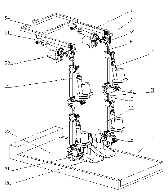
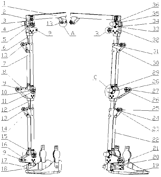
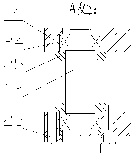
[0030] 1. see figure 1 , figure 2 , image 3 , Figure 4 , Figure 5 , Figure 6 , Figure 7 , Figure 8 , Figure 9 , a mechanical leg for gait training, including a treadmill (I) and two sets of single-leg simulation devices (II), characterized in that:
[0031] 1) The two single-leg simulation devices (II) are symmetrically placed side by side on a frame (54), and the frame (54) is fixedly connected with the treadmill (I), so that the two sets of single-leg simulation devices (II) ) the training shoes (19) at the lower end can step on the pedal (55) of the treadmill (1);
[0032] 2) Each set of single-leg simulation device is as follows: a hip joint fixing rod (1) is hinged to an upper thigh block (6) through a hip joint, and the upper thigh block (6) is connected to a lower thigh block (7). Telescopic socket, the thigh lower block (7) is hinged with a calf upper block (12) through a knee joint, the calf upper block (12) is telescopically connected with a calf low...
Embodiment 2
[0036] This embodiment is basically the same as Embodiment 1, and the special feature is that the hip joint fixing rod (1) is fixed and installed on the frame (54) horizontally, and is fixed and installed vertically with the hip joint fixing block (2), and the hip joint is fixed Block (2), joint shaft (5) and hip joint driver connection block (32) form the hip joint structure, angular contact ball bearings (4) are installed at both ends of the joint shaft, and joint bearing outer cover (33) and joint bearing inner The cover (3) covers the angular contact ball bearings (4) at both ends, so that the hip joint driver connection block (32) rotates around the joint axis (5); the lower end of the hip joint driver connection block (32) and the thigh upper block (6) Fixed installation, the lower thigh block (7) is set on the upper thigh block (6), the length of the thigh is adjusted through the latch (30), and the upper and lower thigh blocks are fastened by the fixed handle (31); the ...
Embodiment 3
[0038] This embodiment is basically the same as Embodiment 1, the special feature is that: the driver structure is installed on the skeleton structure of the mechanical leg, its motor (53) is fixedly installed on the bracket plate (47), the screw nut sleeve (39) and The sleeve (40) is fixedly installed on both sides of the bracket plate (47), the end cover (44) and the sleeve (40) are fixedly installed, and the force sensor (45) is screwed between the suspension block (46) and the end cover (44). Between, the small pulley (49) is fixedly installed on the output shaft of the motor (53), the small pulley (49) is connected with the large pulley (48) through the timing belt (50), and the large pulley (48) is fixedly installed on the On the screw nut sleeve (39), the guide sleeve (41) is fixedly installed inside the sleeve (40), one end of the ball screw (38) is screwed with the guide column (42), and the guide column baffle (43) is fixedly installed on the On the guide column (42)...
PUM
 Abstract
Description
Claims
Application Information
 - R&D
- Intellectual Property
- Life Sciences
- Materials
- Tech Scout
- Unparalleled Data Quality
- Higher Quality Content
- 60% Fewer Hallucinations
Browse by: Latest US Patents, China's latest patents, Technical Efficacy Thesaurus, Application Domain, Technology Topic, Popular Technical Reports.
© 2025 PatSnap. All rights reserved.Legal|Privacy policy|Modern Slavery Act Transparency Statement|Sitemap|About US| Contact US: help@patsnap.com


