Continuous automatic tool machining device

A technology of automatic machining and cutting tools, applied in the direction of manufacturing tools, other manufacturing equipment/tools, etc., can solve the problems of inability to directly process long bars into multiple tools, frequent feeding, and complicated processes, so as to improve processing efficiency and reduce The effect of feeding times and reducing costs

Inactive Publication Date: 2013-06-05
KUNSHAN YUNCO PRECISION IND TECH
View PDF5 Cites 1 Cited by
  • Summary
  • Abstract
  • Description
  • Claims
  • Application Information

AI Technical Summary

Problems solved by technology

[0004] In view of the above-mentioned defects and problems that the existing tool processing device cannot directly process long bars into multiple tools, the process is cumbersome, frequent feeding, low e

Method used


Image

  • Continuous automatic tool machining device
  • Continuous automatic tool machining device
  • Continuous automatic tool machining device

Examples


Embodiment Construction

[0036] The technical solutions of the present invention will be clearly and completely described below in conjunction with the accompanying drawings of the present invention. Obviously, the described embodiments are only some of the embodiments of the present invention, not all of them. Based on the embodiments of the present invention, all other embodiments obtained by persons of ordinary skill in the art without creative efforts fall within the protection scope of the present invention.

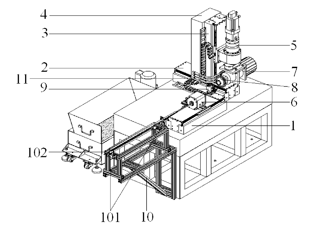
[0037] Such as figure 1 As shown, a tool continuous automatic processing device provided by the embodiment of the present invention includes: X-axis 1, Y-axis 2, Z-axis 3, column 4, first precision rotation axis 5, automatic clamping precision rotation axis 6, main shaft 7. Grinding wheel group 8, support module 9, and support frame 10; the X-axis 1 is fixed on the horizontal plane of the machine tool, and an automatic clamping precision rotating shaft 6 moving along the X-axis direction is...


PUM


Abstract

The invention provides a continuous automatic tool machining device which comprises an auto-clamping precision rotating shaft and a support module. The auto-clamping precision rotating shaft mounted on X-axis comprises a bar clamping module. The bar clamping module comprises a piston cavity located in a rotor adapter, the piston cavity is provided with an air guide hole and a piston post inside. The piston post is connected with a gripper handle through a precision spring. A gripper is fixed on the inner side of a round end cover. The support module mounted on X-axis comprises a Y-axial and Z-axial sliding table, a cylinder and a shaft sleeve. A parallel two-finger clamp serves as an output end of the cylinder. The gripper and the shaft sleeve are collinear and are coordinated with the parallel two-finger clamp to act. The precision rotating shaft has the function of automatic clamping. The support module and a support frame are fitted to two ends of the bar, pneumatic technology is applied, and accordingly continuous automatic machining of tools can be achieved by pre-feeding and simple adjustment. Precision is guaranteed, feeding times are decreased, automation level is increased, and machining efficiency of precision tools is increased and cost is lowered.

Description

technical field [0001] The invention relates to the field of precision tool processing equipment, in particular to a tool continuous automatic processing device. Background technique [0002] As a professional tool for machining precision parts in CNC machine tools, the cutting tool's own precision can have a direct impact on the machining accuracy of the parts. Precision parts are made by cutting off the remaining material of the workpiece through cutting action. During this process, the tool has direct contact and friction with the surface of the part, and it is continuously worn until it is scrapped. Improving the machining accuracy of parts can be achieved by maintaining the sharpness of the cutting edge of the tool and increasing the speed of the tool. However, the latter is mainly related to the key technologies of high-precision rotating spindles, and these technologies are still difficult to obtain. In contrast, reducing the processing cost of cutting tools, improvi...

Claims


Application Information

Patent Timeline
IPC IPC(8): B24B3/00
Inventor 崔华
Owner KUNSHAN YUNCO PRECISION IND TECH
Why Eureka
Try Eureka