Continuous double-horizontal-shaft forced mixer for asphalt and concrete

An asphalt concrete and forced mixer technology, which is applied in clay preparation devices, mixing operation control, cement mixing devices, etc., can solve the problems of reduced equipment productivity, existing material waiting time, inconvenient transportation and installation, etc., and achieves high mixing efficiency and reduced contact. , the effect of small footprint

Active Publication Date: 2013-06-05
FUJIAN SOUTHERN HIGHWAY MECHANICAL
View PDF5 Cites 19 Cited by
  • Summary
  • Abstract
  • Description
  • Claims
  • Application Information

AI Technical Summary

Problems solved by technology

[0002] The traditional batch asphalt mixing equipment still occupies a dominant position in the market, but the batch asphalt mixing equipment has the following disadvantages: first, the process of mixing materials is intermittent, and there is a waiting time, which reduces the productivity of the equipment; second, the equipment Huge, inconvenient for transportation and installation, and long transition period
Third, the existing asphalt mixing equipment is usually a mixing station or a mixing building, with high manufacturing costs, complex structures, large floor space, inconvenient disassembly and assembly, and high maintenance costs
At present, the production output of intermittent twin-shaft forced mixer in the world is only 640t / h, and it is still blank to use continuous twin-shaft forced mixer for road asphalt concrete mixing.

Method used


Image

  • Continuous double-horizontal-shaft forced mixer for asphalt and concrete
  • Continuous double-horizontal-shaft forced mixer for asphalt and concrete
  • Continuous double-horizontal-shaft forced mixer for asphalt and concrete

Examples


specific Embodiment 1

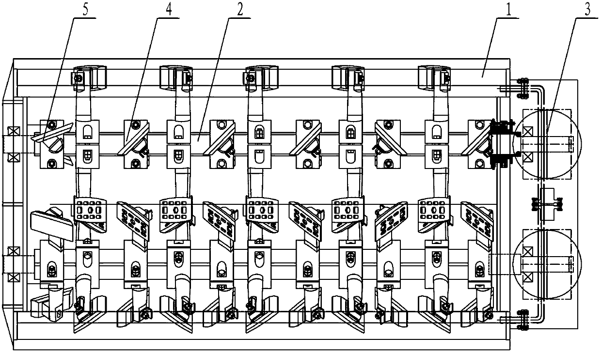
[0032] refer to Figure 1 to Figure 8 As shown, a continuous twin-shaft forced mixer for asphalt concrete includes a mixing tank 1 , a mixing shaft 2 , a driving device 3 , a mixing unit 4 and a scraping unit 5 .

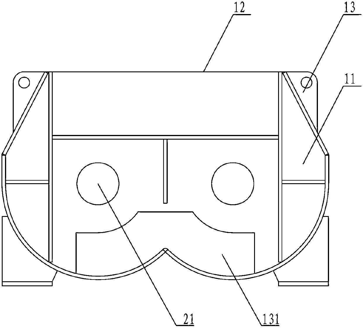
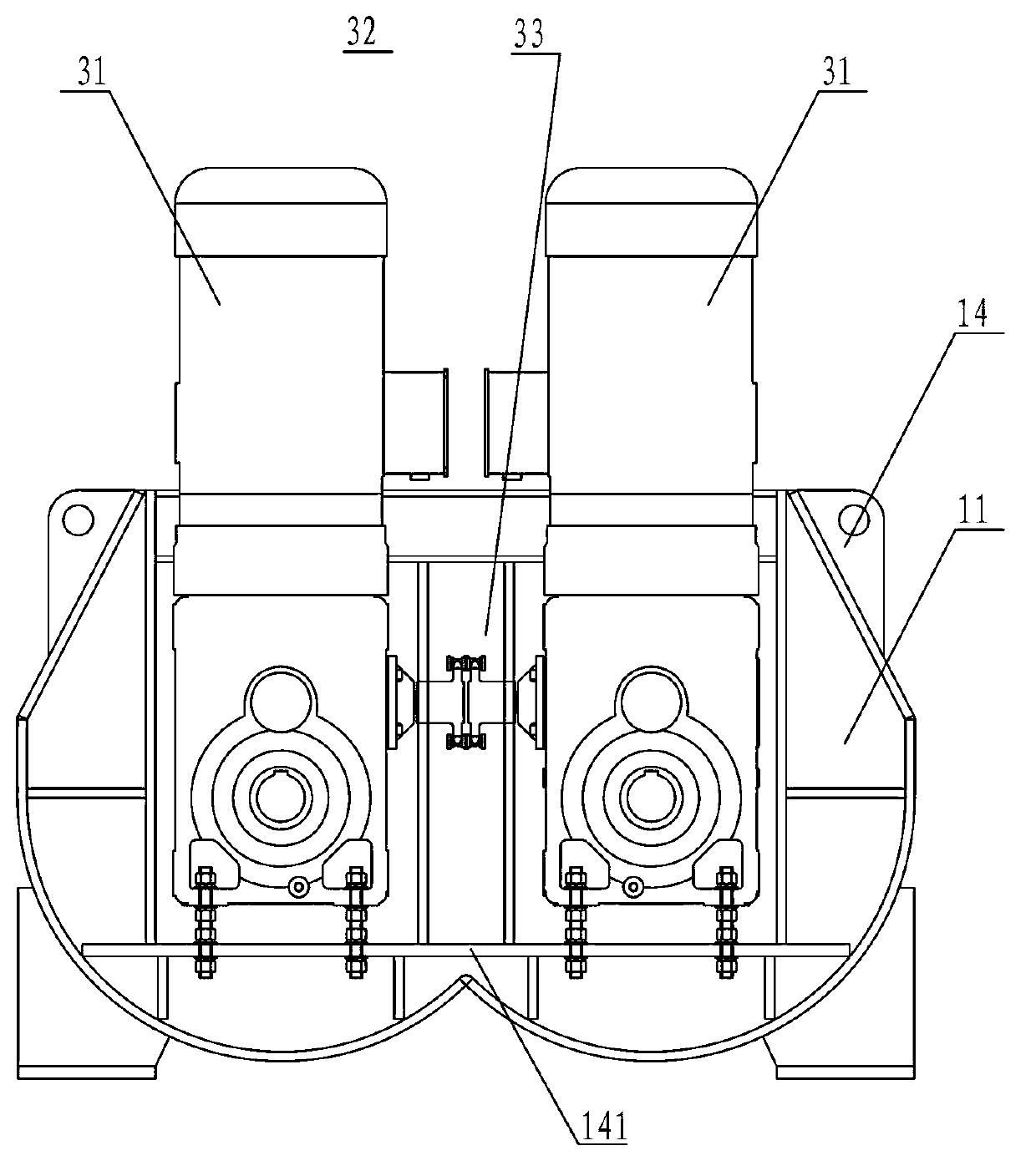
[0033] The mixing cylinder 1 is composed of a mixing cylinder 11, a cylinder upper cover 12, a left side plate 13, and a right side plate 14. The leftmost end of the large arc plate at the bottom of the mixing cylinder 11 has a first discharge port 111, and the cylinder upper cover The right end of 12 has a material inlet 121, the bottom of the left side plate 13 has a second discharge port 131 continuous with the first discharge port 111, and the right side plate 14 is provided with a motor mounting seat 141;

[0034] There are two stirring shafts 2, which are installed in the mixing cylinder 11 in parallel. The left end of the stirring shaft 2 is connected to the shaft end bearing 21 installed on the left side plate 13, and the right end of the stirring shaft 2 is...

specific Embodiment 2

[0038] Specific embodiment two: there are ten stirring groups on each stirring shaft, wherein the ratio of feeding blades and returning blades is adjusted to 8:2, that is, eight groups are equipped with feeding blades, and two groups are equipped with returning blades, and the stirring shaft is fed from From right to left, feed blades, feed blades, feed blades, return blades, feed blades, feed blades, feed blades, feed blades, feed blades, and return blades are installed in turn; two stirring shafts 2 The stirring groups are arranged in a staggered manner to obtain a large shear overlap area. The rest of the components are the same as those in the first embodiment, and will not be repeated here. Compared with the whole mixer, this arrangement of feeding blades and returning blades is suitable for use when the mixing quality of the mixed material is low.

specific Embodiment 3

[0039]Specific embodiment three: ten stirring groups are arranged on each stirring shaft, wherein the ratio of feeding blades and returning blades is adjusted to 6:4. From right to left, feed blades, feed blades, return blades, feed blades, feed blades, return blades, feed blades, return blades, feed blades, and return blades are installed in turn; the stirring on the two stirring shafts 2 The groups are arranged in a staggered manner to obtain a larger clipped overlapping area. The rest of the components are the same as those in Embodiment 1, and will not be repeated here. Compared with the whole mixer, this arrangement is suitable for use when the mixing quality of the mixed material is very high.

[0040] refer to Figure 1 to Figure 8 As shown, the working process of the asphalt concrete continuous twin-shaft forced mixer provided by specific embodiment one, specific embodiment two, and specific embodiment three is as follows:

[0041] The stirring shaft 2 in the mixing ...


PUM


Abstract

The invention belongs to the technical field of asphalt and concrete mixing, and particularly relates to a continuous double-horizontal-shaft forced mixer for asphalt and concrete. The continuous double-horizontal-shaft forced mixer for the asphalt and the concrete comprises a mixing tank provided with a feeding port and a discharging port, two mixing shafts which are arranged in the mixing tank in a parallel mode, a driving device which drives the mixing shafts to rotate synchronously and reversely, a plurality of groups of mixing units and a material scraping unit. Each mixing unit comprises mixing arms and blades, wherein the mixing arms are mounted on the mixing shafts in an opposite mode, the blades are mounted on the mixing arms and comprise a feeding blade and a returning blade, and the feeding blade and the returning blade are the same in structure and size and opposite in mounting direction. The material scraping unit comprises a group of mixing arms which are arranged in an opposite mode, and material scraping blades which are connected on the mixing arms, wherein an acute included angle is formed between each material scraping blade and a side plate of the mixing tank. According to the bituminous mixture mixer, namely the continuous double-horizontal-shaft forced mixer for the asphalt and the concrete, the methods of continuous grading feeding, continuous mixing and continuous discharging are used, and the output of the bituminous mixture mixer can reach 100-1,000 tons per hour.

Description

technical field [0001] The invention belongs to the technical field of asphalt concrete mixing, in particular to a continuous twin-shaft forced mixer for asphalt concrete. Background technique [0002] The traditional batch asphalt mixing equipment still occupies a dominant position in the market, but the batch asphalt mixing equipment has the following shortcomings: First, the process flow of the mixing material is intermittent, and there is a waiting time, which reduces the productivity of the equipment; second, the equipment Huge, inconvenient for transportation and installation, and long transition period. Third, the existing asphalt mixing equipment is usually a mixing station type or a mixing building type, which has high manufacturing cost, complex structure, large floor area, inconvenient disassembly and assembly, and high maintenance cost. [0003] The mixture produced by the continuous mixer has the characteristics of good uniformity, stable operation, large outpu...

Claims


Application Information

Patent Timeline
Patent Type & Authority Applications(China)
IPC IPC(8): B28C5/14B28C7/04B28C7/16
Inventor 丁华鹏汤明陈慕斌全阳娟
Owner FUJIAN SOUTHERN HIGHWAY MECHANICAL
Why Eureka
Try Eureka