Bead type tubular anchor rod

A technology of tubular and anchor rods, which is applied in the installation of anchor rods, sheet pile walls, mining equipment, etc., can solve the problems of inability to provide pull-out resistance, inability to adapt to weak rock and soil immediate support, and failure of rock and soil anchoring. Achieve the effects of improving the load transfer mechanism, optimizing the load transfer mechanism, and speeding up the project progress

Inactive Publication Date: 2015-05-13
LANZHOU UNIVERSITY
View PDF5 Cites 0 Cited by
  • Summary
  • Abstract
  • Description
  • Claims
  • Application Information

AI Technical Summary

Problems solved by technology

[0004] During the construction and operation of rock-soil anchorage, the pull-out of the anchor rod from the grouting body and the pull-out of the anchor rod and the grouting body from the anchor hole are the two most basic rock-soil anchorage failure forms, and they all cause rock-soil anchorage failure. Anchor failure, and bring hidden dangers to engineering safety, thus limiting the pullout force that the anchor can provide
Therefore, when the pull-out force needs to be provided, ordinary bolt anchorage can no longer meet the needs of the project, and it has become a bottleneck restricting the application and development of rock-soil anchorage technology. How to improve the load transfer mechanism of rock-soil anchorage and overcome ordinary friction The disadvantages of type anchoring become the fundamental way to improve the pullout resistance of anchor bolts
[0005] In addition, mortar anchoring can hardly provide pullout resistance at the initial stage, so it cannot meet the requirements of immediate support after excavation of weak rock and soil
Although the existing pipe-slot bolts have overcome the above-mentioned shortcomings, the bolts can provide pull-out force immediately after installation, which is beneficial to timely control the deformation of rock and soil, but the pull-out force that can be provided is not large; at the same time, Due to the weak rock and soil will be squeezed into the pipe cavity from the pipe seam of the pipe seam anchor, resulting in a decrease in pullout resistance
However, the existing hydraulic expansion tube bolt has complex processing technology, inconvenient construction, and less application

Method used


Image

  • Bead type tubular anchor rod
  • Bead type tubular anchor rod
  • Bead type tubular anchor rod

Examples


Embodiment Construction

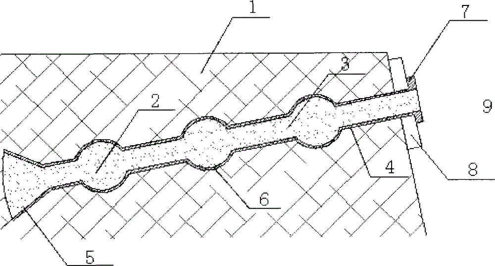
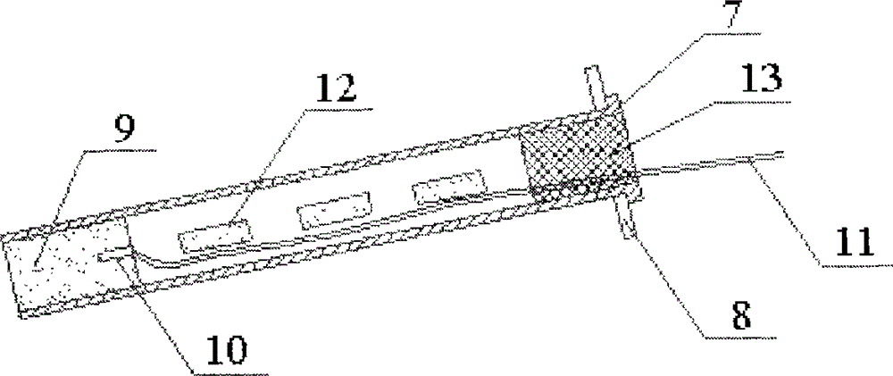
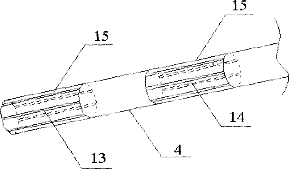
[0018] Such as Figure 1~3 As shown, the beaded tubular anchor rod includes a hollow tubular anchor rod body 4 with openings at both ends, a retaining ring 7 and a backing plate 8 . The bottom end of the tubular anchor rod body 4 is provided with axial grooves 14 penetrating the pipe wall 15 at equal intervals in the axial direction along the circumferential direction, and a retaining ring 7 with a backing plate 8 is provided at the top end thereof.

[0019] Wherein: the bottom end of the tubular anchor rod body 4 is provided with a detonator 9 with a detonator 10 inside the tube wall 15 having an axial groove 14; A cylindrical charge 12 is arranged inside the tubular wall 15 of the tubular anchor body 4 that is equally spaced axially by the axial grooves 14 .

[0020] During use, (1) carry out drilling 3 to weak rock-soil body 1 according to the design requirement; (2) insert tubular anchor rod body 4 in the borehole 3, fill the blasting mud 13 at the top of tubular anchor r...


PUM


Abstract

The invention relates to a bead type tubular anchor rod which comprises a tubular anchor rod body, a stopping ring and a pad plate. Openings are formed at two ends of the tubular anchor rod body which is hollow, axial grooves which penetrate through the tube wall are formed at the bottom end of the tubular anchor rod body along the circumference direction and on the tube wall along the axial direction at intervals, and the stopping ring provided with the pad plate is arranged at the top end of the tubular anchor rod body. The bead type tubular anchor rod is simple in structure, can immediately provide pulling resistance, obtains immediate anchoring effect, simultaneously can obviously optimize and improve load transmission mechanism of ground anchoring, strengthens stability of a ground body, and safety of anchoring on tunnels, side slopes, deep foundation pits and the like is greatly strengthened..

Description

technical field [0001] The invention relates to rock-soil anchoring technology, in particular to a beaded tubular anchor rod. Background technique [0002] Rock-soil anchoring is to tightly interlock the strata through the anchor bolts buried in the formation, relying on the interaction between the anchor bolt-grouting body-hole wall rock-soil physical force to mobilize and improve the rock-soil mass's own strength and natural strength. It is a technology to improve the stress state and ensure the stability of the external rock and soil mass, thereby ensuring the safety of the project. The application of geotechnical anchoring technology in geotechnical-related engineering can be traced back to the end of the 19th century. With the development of its theoretical research and engineering applications, geotechnical anchoring technology has been widely used in mines, water conservancy, hydropower, roads, railways, municipal As an ideal form of support, it plays an important ro...

Claims


Application Information

Patent Timeline
Patent Type & Authority Patents(China)
IPC IPC(8): E02D5/74E21D21/00
Inventor 言志信任志华
Owner LANZHOU UNIVERSITY
Why Eureka
Try Eureka