

High-efficiency oil separator
An oil separator and oil separation technology, applied in the field of oil separation devices and high-efficiency oil separators, can solve the problems of insufficient lubrication, large volume and low oil separation efficiency, and achieve the effect of small footprint and compact overall structure.
- Summary
- Abstract
- Description
- Claims
- Application Information
AI Technical Summary
Problems solved by technology
Method used
Image

Examples
Embodiment Construction
[0024] The present invention will be further described below in conjunction with accompanying drawing:
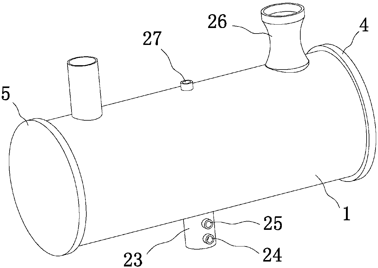
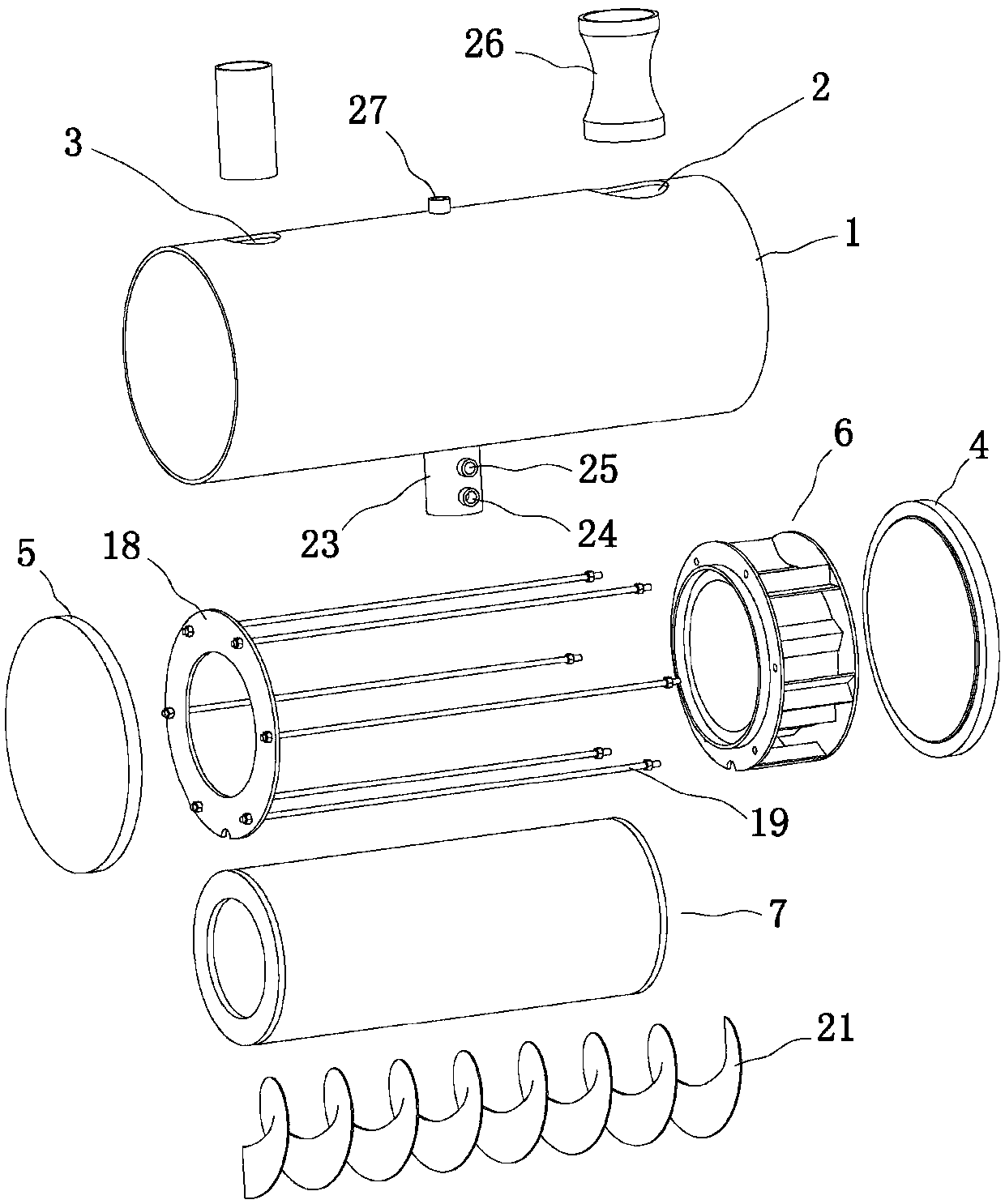
[0025] Referring to the accompanying drawings: this high-efficiency oil separator in this embodiment includes a main cylinder body 1 and air inlet holes 2 and air outlet holes 3 respectively arranged on the side walls at both ends of the main cylinder body 1, and the two ends of the main cylinder body 1 The front sealing plate 4 and the rear sealing plate 5 are respectively provided, and the oil separation retaining cylinder 6 and the filter cylinder 7 connected in sequence are arranged in the main cylinder body 1,
[0026] The oil separation retaining cylinder 6 includes an inner cylinder 9 located inside one end of the main cylinder body 8. The two ends of the inner cylinder 9 are respectively provided with a front side plate 10 and a rear side plate 11. The inner wall of the main cylinder body 8, the outer wall of the inner cylinder 9, the front A channel 12 for the circ...
PUM
 Abstract
Description
Claims
Application Information