
Power supply line fault monitoring device

A power supply line and fault monitoring technology, applied in the direction of the fault location, etc., can solve the problems that the power supply line affects the transmission of "electricity", the normal use of electrical equipment, and the theft of power supply lines and cables of street lights, etc., to save manpower, low cost, Timely effect of fault point alarm

Inactive Publication Date: 2013-06-05
王翥
View PDF5 Cites 3 Cited by
  • Summary
  • Abstract
  • Description
  • Claims
  • Application Information

AI Technical Summary

Problems solved by technology

[0002] People's daily life is inseparable from "electricity", and the transmission of "electricity" cannot be separated from the power supply line. Failure of the power supply line will directly affect the transmission of "electricity", and then affect the normal use of electrical equipment
For example, after a cable disconnection fault occurs on the street lamp power supply line, all street lamps after the fault point will not work normally, which will bring great inconvenience to urban night life. If time is discovered and repaired, it will not only affect the normal use of electrical equipment, but also bring immeasurable property losses to the country
At present, there is no good way to quickly, timely and accurately obtain fault information of power supply lines

Method used


Image

  • Power supply line fault monitoring device
  • Power supply line fault monitoring device
  • Power supply line fault monitoring device

Examples


Embodiment 1

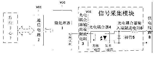
[0030] A power supply line fault monitoring device, the power supply line provides 220V50Hz alternating current. As we all know, at this time, the working current of the current limiting resistor 6 at the input end of the optocoupler is an AC current i ,Alternating current i The change period is also 50Hz, such as Figure 5 , Figure 6 As shown by the dotted line, it will not be repeated here.

[0031] Such as figure 1 As shown, the current-limiting resistor 3 at the output end of the optocoupler is a circuit form of a pull-up resistor. When the power supply line 8 is in a normal working state, the power supply line 8 will have an AC voltage, and the AC voltage will pass through the current-limiting resistor 6 at the input end of the optocoupler. The light-emitting diode in the photocoupler 4 and the diode 5 form a loop and generate an alternating current. When the flow direction of the alternating current is consistent with the conduction direction of the light-emitting d...

Embodiment 2

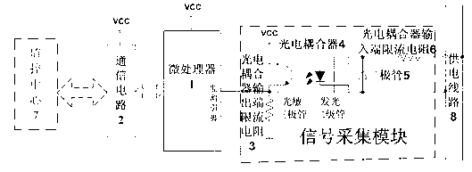
[0034] A power supply line fault monitoring device, the power supply line provides 220V50Hz alternating current. As we all know, at this time, the working current of the current limiting resistor 6 at the input end of the optocoupler is an AC current i ,Alternating current i The change period is also 50Hz, such as Figure 5 , Figure 6 As shown by the dotted line, it will not be repeated here.

[0035] Such as figure 2 As shown, the current-limiting resistor 3 at the output end of the optocoupler is a circuit form of a pull-down resistor. When the power supply line 8 is in a normal working state, the power supply line 8 will have an AC voltage, and the AC voltage will pass through the current-limiting resistor 6 at the input end of the optocoupler. The light-emitting diode in the coupler 4 and the diode 5 form a loop and generate an alternating current. When the flow direction of the alternating current is consistent with the conduction direction of the light-emitting dio...


PUM


Abstract

The invention relates to a power supply line fault monitoring device which comprises a microprocessor, a signal collection module and a communication circuit. The signal collection module is composed of a photoelectric coupler, a photoelectric coupler input end current-limiting resistor, a photoelectric coupler output end current-limiting resistor and diodes. When a power supply line works normally, frequency signals are monitored by a monitoring pin of the microprocessor, and therefore whether the power supply line has faults or not is deduced. According to the power supply line fault monitoring device, automatic monitoring and remote alarming of the faults of the power supply line are achieved, the device has the advantages of alarming the faults in time and being high in working efficiency, low in maintenance cost and capable of improving intelligent degree of monitoring of the power supply line.

Description

technical field [0001] The invention relates to a monitoring device, in particular to a power supply line fault monitoring device. Background technique [0002] People's daily life is inseparable from "electricity", and the transmission of "electricity" cannot be separated from the power supply line. Failure of the power supply line will directly affect the transmission of "electricity", and then affect the normal use of electrical equipment. For example, after a cable disconnection fault occurs on the street lamp power supply line, all street lamps after the fault point will not work normally, which will bring great inconvenience to urban night life. If time is discovered and repaired, it will not only affect the normal use of electrical equipment, but also bring immeasurable property losses to the country. At present, there is no good way to quickly, timely and accurately obtain fault information of power supply lines. Contents of the invention [0003] The technical p...

Claims


Application Information

Patent Timeline
Patent Type & Authority Applications(China)
IPC IPC(8): G01R31/08
Inventor 王翥佟晓筠佟少强
Owner 王翥
Learn More