Imaging lens assembly

A lens system and imaging technology, applied in optics, instruments, optical components, etc., can solve the problems of increasing lens cost, long optical total length, difficult assembly, etc., and achieve the goals of reducing sensitivity, short optical total length, and shortening the back focal length Effect

Active Publication Date: 2013-06-05
LARGAN PRECISION
View PDF5 Cites 2 Cited by
  • Summary
  • Abstract
  • Description
  • Claims
  • Application Information

AI Technical Summary

Problems solved by technology

[0003] Most of the existing high-resolution photographic lenses use a front aperture and are a four-piece lens group, such as the four independent lens systems shown in US Pat. (T 12 ) is small, the assembly is not easy, resulting in poor yield, which in turn increases the cost of lens manufacturing
In addition, the second lens thickness (CT 2 ) is large, resulting in a longer total optical length. With the development of electronic products in the direction of light, thin, short, and small, the existing photographic lenses still have the problem of longer total optical length

Method used


Image

  • Imaging lens assembly
  • Imaging lens assembly
  • Imaging lens assembly

Examples


no. 1 example

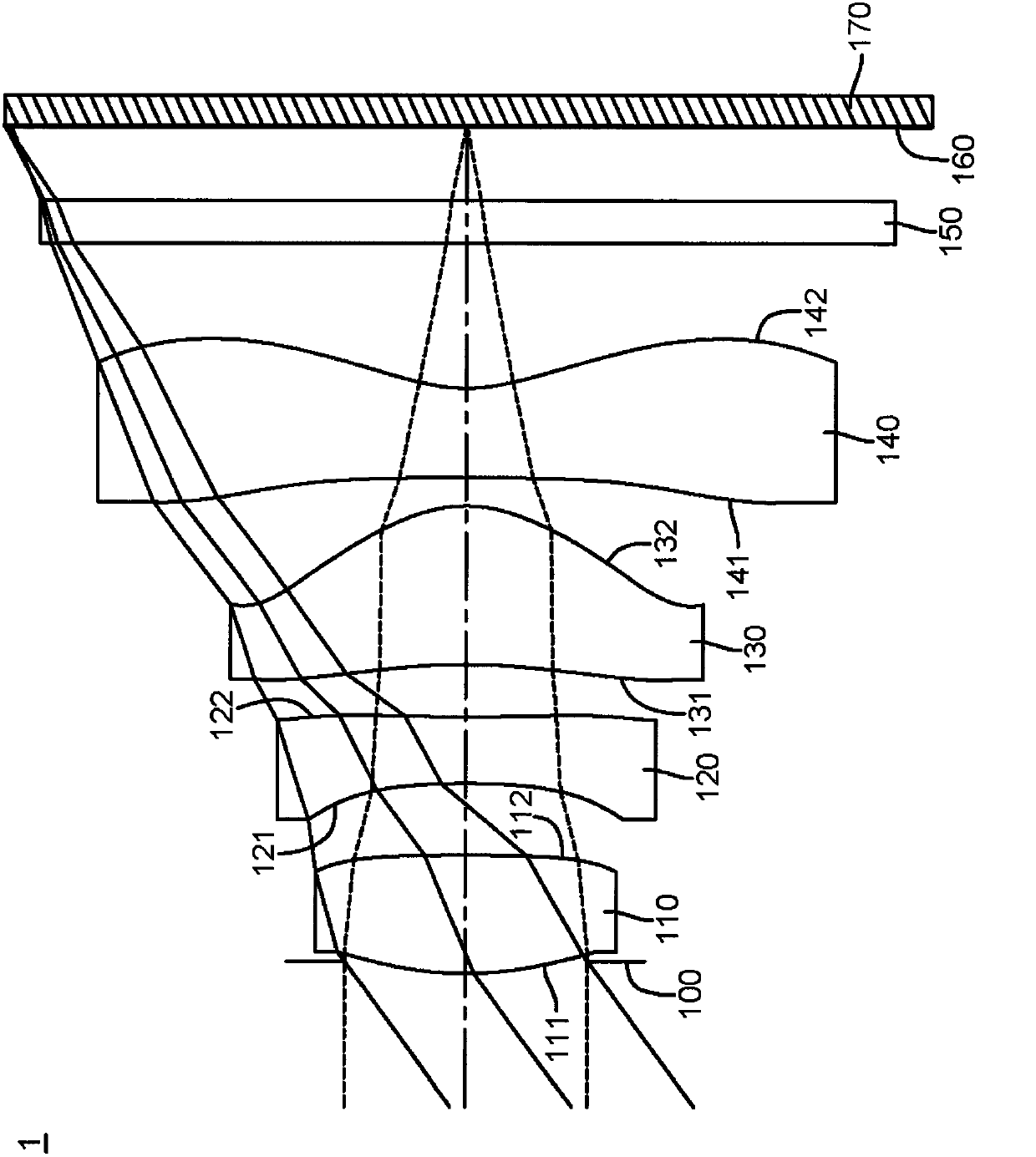
[0105] Please refer to Figure 1A Shown is a schematic structural diagram of the first embodiment of the imaging lens system. The imaging lens system 1 is from the object side to the image side (that is, along Figure 1A from the left side to the right side) sequentially includes an aperture 100, a first lens 110, a second lens 120, a third lens 130, a fourth lens 140, an infrared filter filter 150 and an image sensor The sensing element 170 is disposed on an imaging surface 160 .

[0106] In this embodiment, the wavelength of light received by the imaging lens system 1 is 587.6 nanometers (nm) as an example, however, the above wavelength can be adjusted according to actual needs, and is not limited to the above wavelength value.

[0107] In this embodiment, the first lens 110 has positive refractive power, the second lens 120 has negative refractive power, the third lens 130 has positive refractive power, and the fourth lens 140 has negative refractive power. Wherein, both t...

no. 2 example

[0125] Please refer to Figure 2A As shown, it is a schematic structural diagram of the second embodiment of the imaging lens system disclosed in the present invention. Its specific implementation is substantially the same as the aforementioned first embodiment, which means that it has the same function or structure. To simplify the description, only the differences will be described below, and the rest of the similarities will not be repeated.

[0126] In this embodiment, the first lens 210 has positive refractive power, the second lens 220 has negative refractive power, the third lens 230 has positive refractive power, and the fourth lens 240 has negative refractive power. Wherein, the first lens object side surface 211 is an aspheric convex surface, and the first lens image side surface 212 is an aspheric concave surface. Both the second lens object side 221 and the second lens image side 222 are aspherical concave surfaces. The third lens object side surface 231 is an as...

no. 3 example

[0139] Please refer to Figure 3A Shown is a schematic structural view of the third embodiment of the imaging lens system disclosed in the present invention. Its specific implementation is substantially the same as the aforementioned first embodiment, which means that it has the same function or structure. To simplify the description, only the differences will be described below, and the rest of the similarities will not be repeated.

[0140] In this embodiment, the first lens 310 has positive refractive power, the second lens 320 has negative refractive power, the third lens 330 has positive refractive power, and the fourth lens 340 has negative refractive power. Wherein, both the first lens object side surface 311 and the first lens image side surface 312 are aspherical convex surfaces. Both the second lens object side 321 and the second lens image side 322 are aspherical concave surfaces. The third lens object side surface 331 is an aspherical concave surface, and the thi...


PUM


Abstract

An imaging lens assembly includes, in order from an object side to an image side, a first lens element with positive refractive power having a convex object-side surface, a second lens element with negative refractive power having a concave object-side surface and a concave image-side surface, a third lens element with positive refractive power having a concave object-side surface and a convex image-side surface, and a fourth lens element with negative refractive power having a concave object-side surface and a concave image-side surface. The third lens element and the fourth lens element are aspheric. The fourth lens element has at least one inflection point. By adjusting the distance between the second lens element and the first lens element as well as the thickness of the second lens element, the imaging lens assembly can be easy to be manufactured and assembled without decreasing its imaging quality.

Description

technical field [0001] The invention relates to an imaging lens system, in particular to an imaging lens system applied to a handheld electronic device. Background technique [0002] In recent years, with the rise of portable electronic products with photography functions, the demand for miniature imaging modules has been increasing day by day, and the image sensing elements of general photography lenses are nothing more than Charge Coupled Devices (CCD) or There are two types of Complementary Metal-Oxide Semiconductor Sensor (CMOS Sensor), and with the improvement of semiconductor process technology, the pixel size of the image sensing element is reduced. How to improve the miniaturization of photography under limited space conditions The imaging quality of the lens has become the focus of attention of the industry. [0003] Most of the existing high-resolution photographic lenses use a front aperture and are a four-piece lens group, such as the four independent lens syste...

Claims


Application Information

Patent Timeline
Patent Type & Authority Applications(China)
IPC IPC(8): G02B13/00G02B13/18G02B13/22G02B13/06
CPCG02B13/06G02B1/04G02B13/18G02B13/22G02B9/34
Inventor 蔡宗翰黄歆璇
Owner LARGAN PRECISION
Why Eureka
Try Eureka