Current-limiting protection method and device of resonance circuit

A resonant circuit and resonant current technology, applied in the field of communication, can solve the problem of excessive voltage stress of the full-bridge tube and achieve the effect of improving reliability

Active Publication Date: 2013-06-05
ZTE CORP
View PDF6 Cites 17 Cited by
  • Summary
  • Abstract
  • Description
  • Claims
  • Application Information

AI Technical Summary

Problems solved by technology

[0005] The present invention provides a resonant circuit current limiting protection method and device to at least solve the technical problem in the prior art that the voltage stress of the full bridge tube exceeds the standard caused by continuous wave-by-wave current limiting

Method used


Image

  • Current-limiting protection method and device of resonance circuit
  • Current-limiting protection method and device of resonance circuit
  • Current-limiting protection method and device of resonance circuit

Examples


Embodiment 1

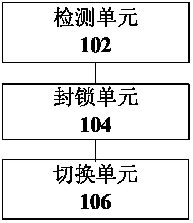
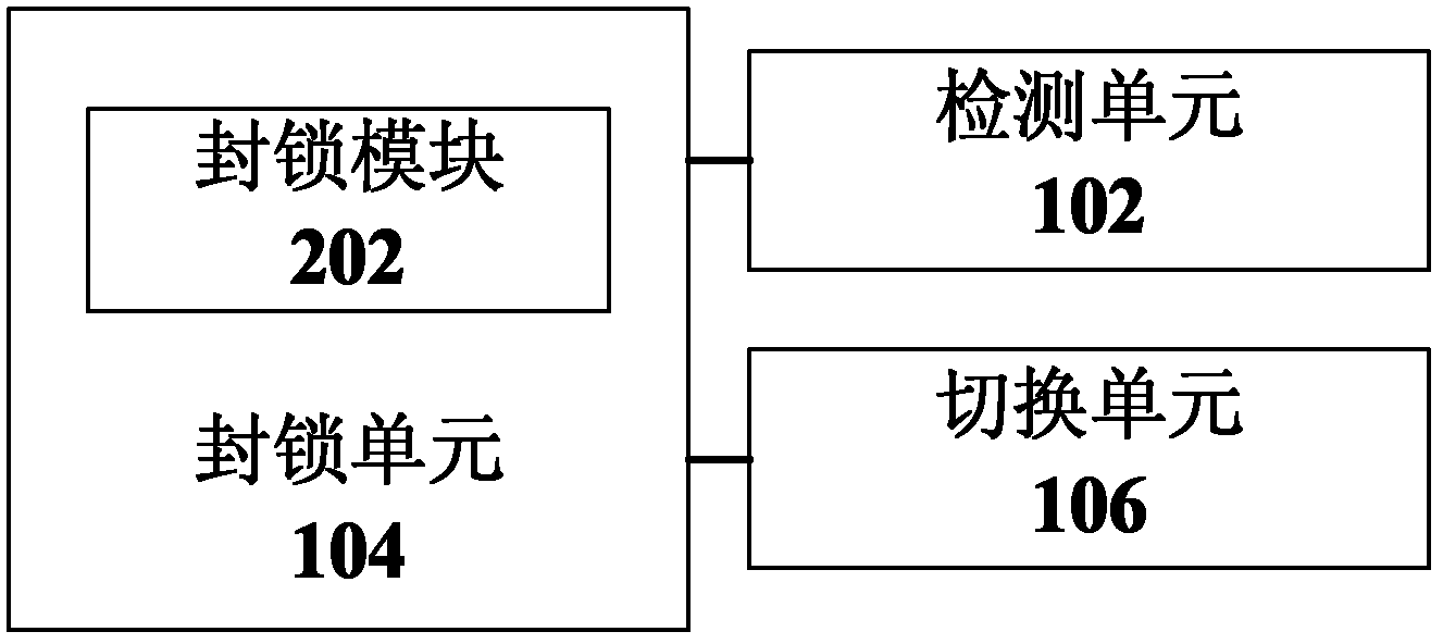
[0031] Such as figure 1 As shown, the present invention provides a preferred resonant circuit current limiting protection device, which includes: a detection unit 102 for detecting the voltage at both ends of the sampling resistor through which the resonant current flows in the resonant circuit; a blocking unit 104 for When it is detected in the current resonance cycle that the voltage across the sampling resistor is greater than a predetermined threshold, the drive of the resonance circuit is blocked; the switching unit 106 is used to switch the resonance circuit from the constant voltage mode when the next pulse width modulation cycle arrives switch to output current limit mode.

[0032] In the above-mentioned preferred embodiment, by adding a strategy in the intelligent unit to make the LLC resonant converter enter the current-limiting loop immediately after the wave-by-wave current limit is detected, the primary current is quickly reduced to within the threshold, and the p...

Embodiment 2

[0041] Based on the devices and circuits shown in 1-7, the present invention also provides a preferred resonant circuit current limiting protection method, such as Figure 8 As shown, the method specifically includes:

[0042] S802: detecting the voltage across the sampling resistor through which the resonant current flows in the resonant circuit;

[0043] S804: When it is detected that the voltage across the sampling resistor is greater than a predetermined threshold in the current resonance period, blocking the drive of the resonance circuit;

[0044] S806: Switch the resonant circuit from the constant voltage mode to the output current limiting mode when the next pulse width modulation period arrives.

[0045] In the above-mentioned preferred embodiment, by adding a strategy in the intelligent unit to make the LLC resonant converter enter the current-limiting loop immediately after the wave-by-wave current limit is detected, the primary current is quickly reduced to within...

Embodiment 3

[0054] The present invention provides a preferred embodiment to further explain the present invention, but it should be noted that the preferred embodiment is only for better describing the present invention and does not constitute an improper limitation of the present invention.

[0055] The present invention will be further described in detail below through specific embodiments and in conjunction with the accompanying drawings.

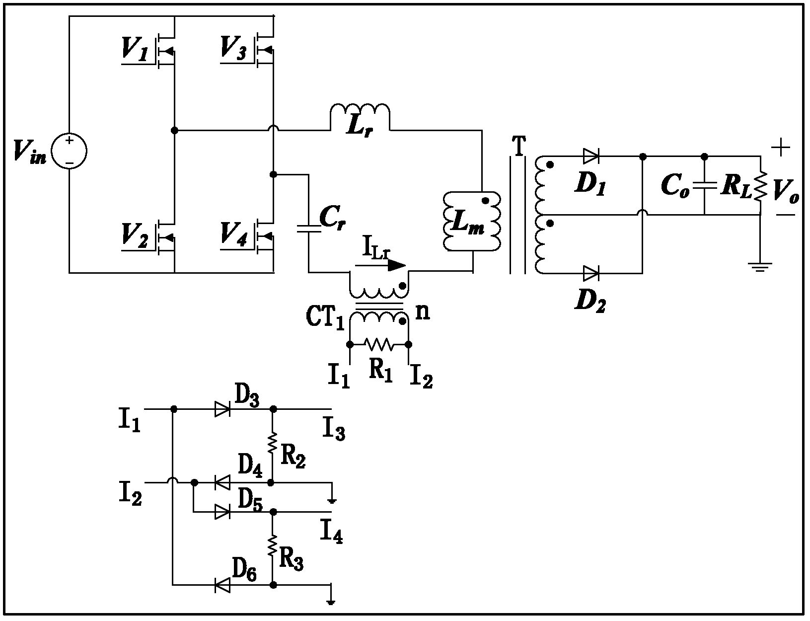
[0056] Such as image 3 As shown, an LLC resonant circuit includes a resonant inductor Lr, a main transformer T, a resonant capacitor Cr, main power switching devices V1, V2, V3 and V4, and secondary power Schottky diodes D1 and D2.

[0057] The resonant current detection circuit includes: current transformer CT1, magnetic reset resistor R1 of CT1, diodes D3, D4, D5 and D6. Preferably, the diodes use fast recovery diodes or Schottky diodes and current sampling resistors R2 and R3. The resonant circuit is connected to a DC input voltage Vin, the ma...


PUM


Abstract

The invention discloses a current-limiting protection method and a device of a resonance circuit. The method comprises the steps of detecting voltages of two ends of a sampling resistor flowed through by a resonance current in the resonance circuit, blocking drive of the resonance circuit when the detected voltages of the two ends of the sampling resistor on a current resonance period are larger than a preset threshold value, and switching the resonance circuit from a constant mode to an output current-limiting mode when a next pulse width modulation period arrives. A strategy of the current-limiting protection method and the device of the resonance circuit that when wave-following limit currents are detected, a logical link control (LLC) resonant converter is enabled to immediately enter a current-limiting mode in control and enables a primary side current to rapidly drop within the threshold value, the technical problem that voltage stress of a full-bridge tube exceeds the standard due to continuous wave-following current limiting is solved, and reliability of a switch power source and reliability of power devices are improved.

Description

technical field [0001] The present invention relates to the communication field, in particular to a resonant circuit current limiting protection method and device. Background technique [0002] High efficiency, high power and high density are an important development trend of power electronic products. Full-bridge LLC resonant DC / DC converters are favored by many people in the switching power supply industry due to their outstanding advantages in conversion efficiency and power density. [0003] At present, for the full-bridge LLC resonant DC / DC converter, when wave-by-wave current limiting occurs, the four drivers of the full-bridge tube of the LLC converter are blocked, and these four drivers are restarted after a period of time. When the wave-by-wave current limiting occurs, the four drivers of the full-bridge tube are blocked immediately, and the full-bridge LLC resonant circuit will enter a self-resonant state. When the downtube of the full-bridge super-forearm is perf...

Claims


Application Information

Patent Timeline
Patent Type & Authority Applications(China)
IPC IPC(8): H02M3/338H02M1/32H02H7/10
CPCH02M1/32H02H7/10H02M2001/0058H02M2001/0009H02M3/3376Y02B70/1433H02M3/335Y02B70/1491H02M1/0009H02M1/0058Y02B70/10Y02P80/10
Inventor 万正海王明金李俊凯
Owner ZTE CORP
Why Eureka
Try Eureka