
Corn threshing machine

A threshing machine and corn technology, applied in threshing equipment, agricultural machinery and tools, applications, etc., can solve problems such as heterogeneity, blockage, and difficult production, and achieve simplified position adjustment mechanism, good technical and economic value, and increase market competition force effect

Inactive Publication Date: 2015-04-15
CHONGQING TIANPO MACHINERY MFG
View PDF6 Cites 0 Cited by
  • Summary
  • Abstract
  • Description
  • Claims
  • Application Information

AI Technical Summary

Problems solved by technology

[0007] a. The corn cobs often jump during the process of moving from the feed end to the threshing end, which leads to poor guiding effect and low feeding speed, and the reason for the corn cobs to jump is because of excessive friction Small;
[0008] b. The corn cob cannot be well stressed on the threshing arc surface on the left bin shell, so it is not easy to threshing;
[0009] c. It is difficult for the corncob to pass through the corncob outlet on the discharge baffle, and more often it is accumulated and blocked at the discharge baffle, so that the corncob cannot be discharged in time, resulting in a low discharge speed
[0010] 2. Although the existing manual eccentric position adjustment mechanism can adjust the position of the upper housing according to the size of the corn cob, the manual eccentric position adjustment mechanism has many parts, complex structure, heterogeneity, and great difficulty in production. Therefore, it is urgent to solve the above-mentioned technology question

Method used


Image

  • Corn threshing machine
  • Corn threshing machine
  • Corn threshing machine

Examples


Embodiment Construction

[0041] The present invention will be further described below in conjunction with the drawings and embodiments:

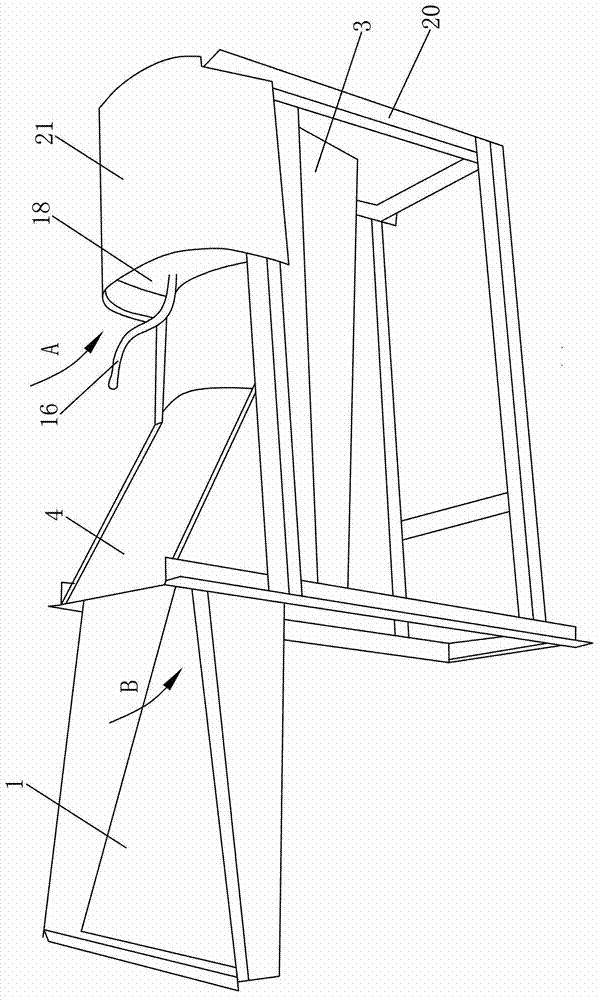
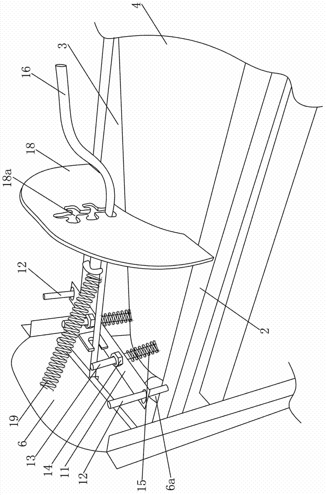
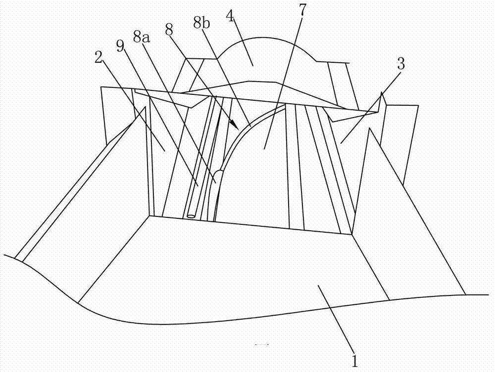
[0042] Such as Figure 1 to 4 As shown, a corn thresher is mainly composed of a feeding hopper 1, a left silo shell 2, a right silo shell 3, an upper silo shell 4, a grain output hopper 5, a discharge baffle 6, a threshing drum 7, and a spiral guide rib 8. The threshing gear lever 9, the discharging stopper 10 and the position adjustment mechanism. Wherein, the feeding hopper 1 is fixed at the feeding ends of the left silo shell 2 and the right silo shell 3, and the lower ends of the left silo shell 2 and the right silo shell 3 are fixedly connected with the lower silo shell (not shown in the figure) , And the left warehouse shell 2, the right warehouse shell 3 and the lower warehouse shell are fixedly supported on the frame 20.

[0043] The upper silo shell 4 is located between the left silo shell 2 and the right silo shell 3. The left side of the feed end of the uppe...


PUM


Abstract

The invention discloses a corn threshing machine. An upper cabin shell is located between a left cabin shell and a right cabin shell; a position adjustment mechanism is arranged on a threshing end of the upper cabin shell; a corn discharge hopper is fixedly arranged on the threshing end of the left cabin shell; a material discharge baffle plate is fixedly arranged between a material discharge end of the left cabin shell and a material discharge end of the right cabin shell; a threshing rotary drum is installed in a chamber formed by the left cabin shell, the right cabin shell, the upper cabin shell and a lower cabin shell; a spiral guide rib is fixedly arranged on the outer wall of the threshing rotary drum; the spiral guide rib consists of a first steel bar section and a second steel bar section; the diameter of the first steel bar section is 8mm to 10mm; the diameter of the second steel bar section is 5mm to 6mm; a ratio of the spread length of the first steel bar section to the spread length of the second steel bar section is 1:3; and a threshing gear rod is fixedly arranged on the threshing arc surface of the left cabin shell. The corn threshing machine improves the threshing efficiency through three aspects, improving the material feeding speed, facilitating the stress of corn cobs and improving the material discharge speed; additionally, the position adjustment mechanism of the upper cabin shell is simplified, so that the manufacture and the implementation are facilitated.

Description

Technical field [0001] The invention belongs to the field of agricultural machinery, and specifically relates to a corn thresher. Background technique [0002] As we all know, corn thresher is a widely used small agricultural machinery. The existing corn thresher mainly includes a feed hopper, a left bunker shell, a right bunker shell, and an upper bunker shell, among which the feed hopper is arranged at the feed ends of the left bunker shell and the right bunker shell. The upper silo shell is located between the left silo shell and the right silo shell, and the two sides of the feed end of the upper silo shell are hinged with the corresponding silo shell, and the threshing end of the upper silo shell is provided with a manual eccentric position adjustment mechanism. Under the action of the position adjustment mechanism, the threshing end of the upper bin shell can swing up and down around its hinged end. In addition, the threshing end of the left silo shell is fixedly provided...

Claims


Application Information

Patent Timeline
Patent Type & Authority Patents(China)
IPC IPC(8): A01F11/06
Inventor 苏公成苏功华
Owner CHONGQING TIANPO MACHINERY MFG
Learn More