High-flow anti-blockage drainage pipe

A large flow, catheter technology, applied in the direction of the catheter, etc., can solve the problems of easy blockage of the closed section, easy suction and injury of human tissue, etc.

Inactive Publication Date: 2013-06-12
郑州迪奥医学技术有限公司
View PDF8 Cites 6 Cited by
  • Summary
  • Abstract
  • Description
  • Claims
  • Application Information

AI Technical Summary

Problems solved by technology

[0002] In the drainage catheter in the prior art, the drainage holes are generally circular holes, which are evenly distributed on the inner end of the tube body. When such drainage holes are in contact with human tissue, they are easy to suck human tissue. Chinese patent: 200920167107.X publication A non-transitional deformation medical catheter, the catheter in this patent uses a strip groove as the drainage port, which successfully solves this problem and can minimize the damage to human tissue, and its flow capacity is compared with that of a circular tube. The duct with the shaped hole as the drainage hole has been improved a lot, but the closed section of the duct still has the problem of being easily blocked when it is folded, and there is still room for improvement in the flow capacity

Method used


Image

  • High-flow anti-blockage drainage pipe
  • High-flow anti-blockage drainage pipe
  • High-flow anti-blockage drainage pipe

Examples


Embodiment 1

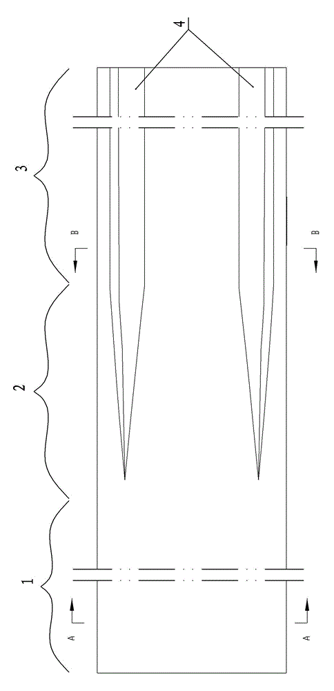
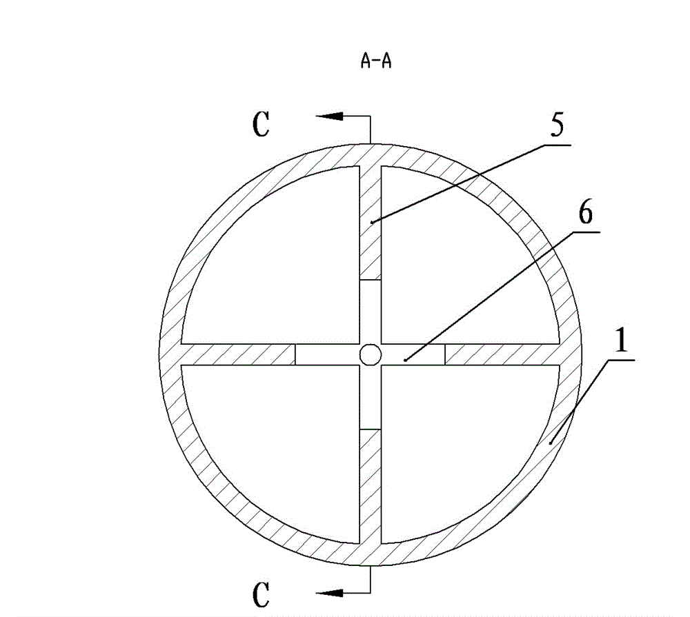
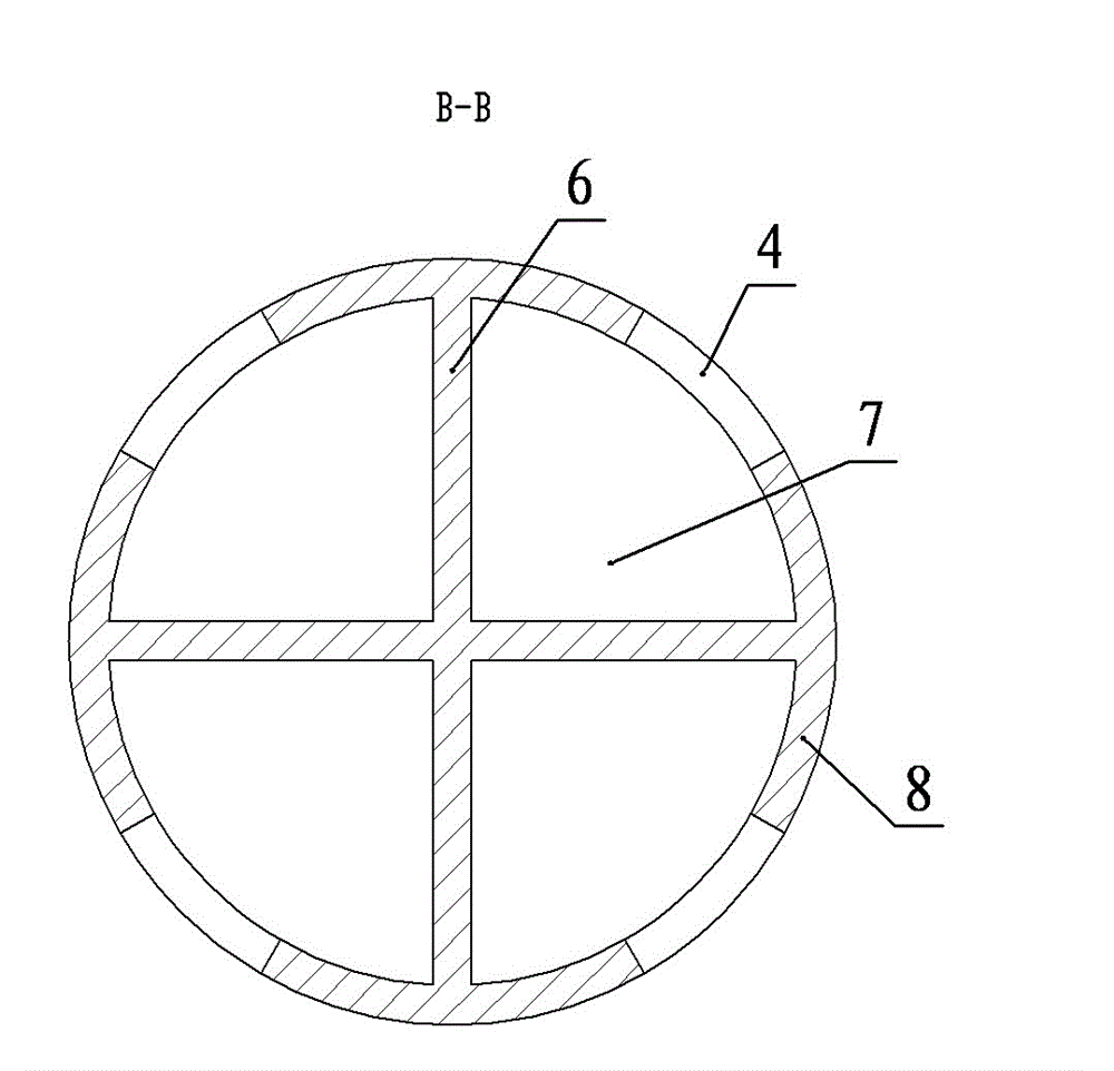
[0019] Embodiment one: see Figure 1-5 , a large-flow anti-blocking drainage catheter in the figure, including a grooved pipe section, a closed pipe section, and a transition section connecting the two. The inside of the grooved pipe section is a radial support body that divides the cross-section of the pipe into N fan-shaped areas The drainage channel, the outer wall of the pipe is provided with N strip-shaped notches corresponding to the fan-shaped area as the drainage port, and the inside of the closed pipe is provided with N ribs protruding toward the axis, and the ribs inside the transition section It is integrated with the support body, N=4. The strip-shaped notch extends along the generatrix direction of the outer wall of the pipe. The width of the strip-shaped notch is smaller than the arc length of the fan-shaped area, and arc-shaped edges are respectively provided on both sides of the notch. The ribs extend along the generatrix direction of the inner wall of the tu...

Embodiment 2

[0020] Embodiment two: see Image 6 , a large-flow anti-blocking drainage catheter, including a grooved pipe section, a closed pipe section, and a transition section connecting the two, characterized in that the grooved pipe section is internally radially supported to divide the cross-section of the pipe into N sectors The drainage channel of the area, the outer wall of the tube is provided with N strip-shaped notches corresponding to the fan-shaped area as the drainage port, and the inside of the closed pipe is provided with N ribs protruding toward the axis, and the inside of the transition section The ribs are integrated with the support body, N=4. The strip-shaped notch extends spirally around the pipe axis, which can increase the area of ​​the drainage port per unit length and improve the flow capacity. The width of the strip-shaped notch is smaller than the arc length of the fan-shaped area, and arc-shaped edges are respectively provided on both sides of the notch. The...


PUM


Abstract

The invention relates to a high-flow anti-blockage drainage pipe comprising an outer slotted pipe section, a closed pipe section and a transition section which connects the two pipe sections; the inside of the slotted pipe section is a drainage channel in which radial support bodies divide the cross section of the pipe into N sector areas; the outer wall of the pipe body is provided with N strip-shaped notches which correspond to the sector areas as drainage ports; N ribs which are protruded to an axis are arranged in a closed pipeline; and in the transition section, the ribs are connected with the support bodies, and N is more than or equal to 3. The drainage pipe has high flow, the ribs are arranged in the closed pipeline, and the high-flow anti-blockage drainage pipe has flow capacity and high anti-blockage performance after being bent.

Description

technical field [0001] The invention relates to the technical field of medical catheters, in particular to a large-flow anti-blocking drainage catheter. Background technique [0002] In the drainage catheter in the prior art, the drainage holes are generally circular holes, which are evenly distributed on the inner end of the tube body. When such drainage holes are in contact with human tissue, they are easy to suck human tissue. Chinese patent: 200920167107.X publication A non-transitional deformation medical catheter, the catheter in this patent uses a strip groove as the drainage port, which successfully solves this problem and can minimize the damage to human tissue, and its flow capacity is compared with that of a circular tube. The duct with the shaped hole as the drainage hole has been improved a lot, but the closed section of the duct still has the problem of being easily blocked when it is discounted, and there is still room for improvement in the flow capacity....

Claims


Application Information

Patent Timeline
Patent Type & Authority Applications(China)
IPC IPC(8): A61M25/14
Inventor 王沛荆文普余勇
Owner 郑州迪奥医学技术有限公司
Why Eureka
Try Eureka