Four-guide pillar type crank shaft flying shear

A technology of crankshaft and flying shears, which is applied in the field of flying shears, can solve the problems of low precision of flying shears, and achieve the effects of high guiding precision, fast and effective cutting, and high applicable frequency

Active Publication Date: 2015-04-22
JINAN EAGLE CNC MASCH CO LTD
View PDF7 Cites 0 Cited by
  • Summary
  • Abstract
  • Description
  • Claims
  • Application Information

AI Technical Summary

Problems solved by technology

[0003] In order to solve the deficiencies of the prior art, the present invention provides a four-column type crankshaft flying shear, provides a flying shear with a more optimized structure, and solves the problem of the accuracy of the existing crankshaft rotary flying shears. not high problem

Method used


Image

  • Four-guide pillar type crank shaft flying shear
  • Four-guide pillar type crank shaft flying shear
  • Four-guide pillar type crank shaft flying shear

Examples


Embodiment Construction

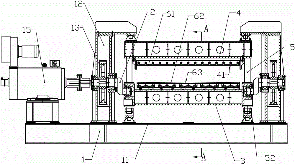
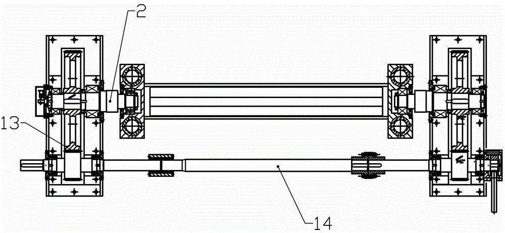
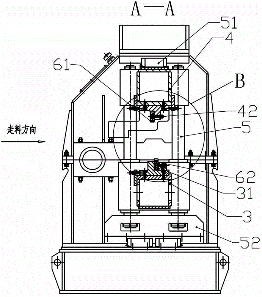
[0017] Such as Figure 1 to Figure 6 as shown,

[0018] A four-column type crankshaft flying shear comprises a machine base, an upper knife rest, a lower knife rest, a crankshaft, a driving motor, a gear transmission mechanism and upper and lower flying shears.

[0019] The base 1 includes a base 11 and a gear box 12 installed on both sides of the base. Two groups of helical gear assemblies 13 are installed in the gear box. Motor 15 is directly connected directly by shaft coupling, and bull gear is arranged on the outer end of crank shaft, and crank shaft 2 is installed in the gear box by bearing, and two crank shafts 2 are connected on both sides of lower tool rest 3 by bearing simultaneously. In this way, the entire transmission system is formed.

[0020] The drive motor 15 drives the two crank shafts to rotate through the gear transmission mechanism, and the flying shears are installed on the upper and lower tool rests to realize the effect of the flying shears.

[0021]...


PUM


Abstract

The invention relates to a four-guide pillar type crank shaft flying shear which comprises a base, an upper knife rest, a lower knife rest, crank shafts, a driving motor, a gear transmission mechanism and a flying shear, and is characterized by further comprising four vertically arranged circular guide pillars, wherein the guide pillars are divided into two groups and the two ends are respectively and fixedly arranged on upper and lower straight sliding rails; the upper knife rest is fixedly arranged on the upper parts of the guide pillars; the lower knife rest is sleeved on the middle lower parts of the guide pillars through straight guide sleeves; and two crank shafts are synchronously jointed on the two sides of the lower knife rest through bearings. According to the invention, the four guide pillars are matched with the straight guide sleeves, so as to realize the guiding for the lower knife rest. Compared with the traditional idler wheel type guiding, the guiding has the characteristics of high guiding precision and high applicable frequency.

Description

technical field [0001] The invention relates to a flying shear for metal coils and plates, in particular to a four-column crankshaft flying shear. Background technique [0002] The closest thing to the present invention is a crankshaft rotating flying shear. For the specific structure, please refer to the literature disclosed in Chinese Patent 2007200179267, which describes the working process and principle of this kind of equipment in detail. The flying shear of this kind of structure Compared with the traditional flying shear machine, the machine has obvious advantages, but there are still some problems in the process of use. The main performance is that the sliding fit is realized through the rollers set laterally between the lower tool holder and the left and right guide rails. In the process of use, the rollers and raceways are prone to wear and tear, resulting in a loose fit between the upper and lower scissors, which affects the quality of the notch. In addition, the...

Claims


Application Information

Patent Timeline
Patent Type & Authority Patents(China)
IPC IPC(8): B23D25/08B23D33/00
Inventor 乔杰云董占魁
Owner JINAN EAGLE CNC MASCH CO LTD
Why Eureka
Try Eureka