Valve body blank

A valve body, blank technology, applied in valve details, valve device, valve shell structure and other directions, can solve the problems of insufficient hydraulic pressure, small flow, and many materials, and achieve the effect of large liquid flow, material saving, and high promotion value.

Active Publication Date: 2015-07-22
南通华东油压科技有限公司
View PDF3 Cites 0 Cited by
  • Summary
  • Abstract
  • Description
  • Claims
  • Application Information

AI Technical Summary

Problems solved by technology

[0004] In order to solve the above problems, the purpose of the present invention is to provide a valve body blank, which solves the problems of many materials, small flow rate and insufficient hydraulic pressure in the prior art.

Method used


Image

  • Valve body blank
  • Valve body blank
  • Valve body blank

Examples


Embodiment Construction

[0020] In order to further illustrate the present invention, describe in detail below in conjunction with accompanying drawing:

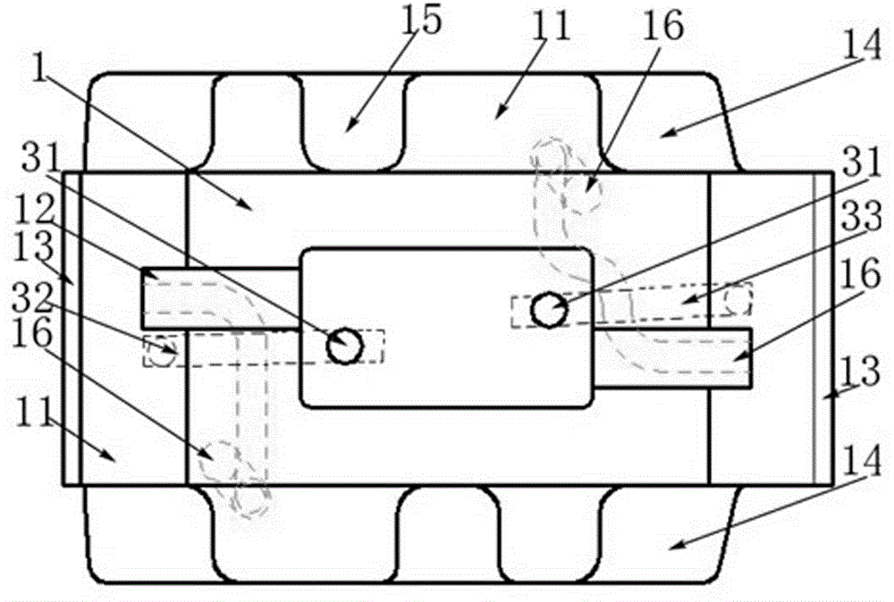
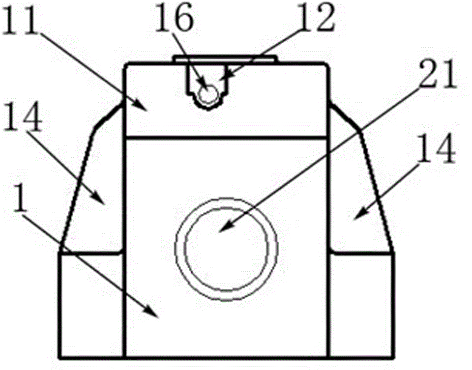
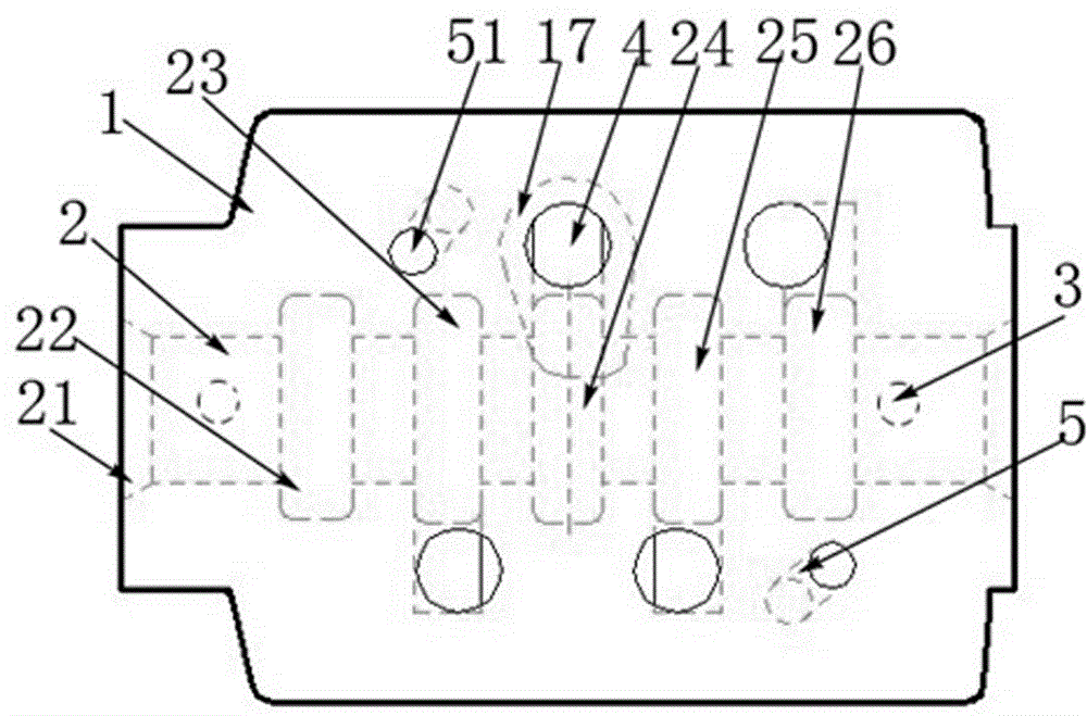
[0021] Referring to the figure below, a valve body blank 1 has a flow channel cast inside it. The flow channel includes a main flow channel 2, a control flow channel 3 and an oil inlet flow channel 4. The main flow channel 2 is located in the middle of the valve body and runs through the valve body horizontally. The flow channel 3 is located above the main channel 2, that is, the upper end of the valve body, and the oil inlet channel 4 is located below the main channel 2, that is, the lower end of the valve body. The four corners of the upper end of the valve body blank 1 are slope surfaces 11, and the upper end two There is a rectangular protrusion 12 in the middle of the slope surface 11 on both sides of the short corner, and there is a section of platform 13 on the edge of the slope surface 11, and there are '∟' grooves 14 on both sides of the upp...


PUM


Abstract

The invention relates to a directional control valve, in particular to a valve body blank, which comprises a main flow passage, control flow passages and oil inlet flow passages, wherein the main flow passage is arranged in the middle of a valve body, the control flow passages are arranged above the main flow passage and the oil inlet flow passages are arranged below the main flow passage. Four edges at the upper end of the valve body are slope surfaces. Two rectangular bulges are respectively arranged adjacent to the middle positions on the slope surfaces on the two sides of two short edges at the upper end. A platform is arranged on the edge of each slope surface. L-shaped grooves are arranged on the two sides of the long edges at the upper end, i.e. at four corners. Semicircular grooves are arranged in the middle of the long edges. An upper end surface is provided with two control oil holes. A left end surface and a right end surface are respectively provided with two flow passage holes, i.e. an auxiliary oil hole and a main flow passage hole, wherein auxiliary oil holes are respectively formed in the rectangular bulges of the slope surfaces of the upper end, and main flow passage holes are respectively formed in the middle and the edges of the main flow passage holes are bell-mouth-shaped. A lower end surface is provided with two auxiliary oil holes and four oil inlets, wherein the two auxiliary oil holes and the four oil inlets are transversely arranged in two rows at positions close to two sides. The drift diameter of the oil inlet flow passages is phi 28mm. The valve body blank has the advantages of simple structure, material saving, large flow and enough hydraulic force.

Description

technical field [0001] The invention relates to a directional control valve, in particular to a valve body blank. Background technique [0002] The development of valve body blanks in the international professional field has gone through more than 50 years, and the application occasions are becoming more and more extensive. The technical level of many types of valve body blanks is very mature. However, some valve body blanks still have some shortcomings during use. [0003] At present, in the prior art of the valve body blank, there are two diameters of the oil inlet channel inside the valve body, one is a diameter of ? ; The other is a diameter of ? 32mm. This large aperture leads to more materials, waste of resources, and high cost. Contents of the invention [0004] In order to solve the above problems, the purpose of the present invention is to provide a valve body blank, which solves the problems in the prior art such as many materials used, small flow rate and...

Claims


Application Information

Patent Timeline
Patent Type & Authority Patents(China)
IPC IPC(8): F16K27/00
Inventor 沈新华马建华
Owner 南通华东油压科技有限公司
Why Eureka
Try Eureka